
Battery pack of improved stability

a battery pack and stability technology, applied in the field of battery pack stability improvement, can solve the problems of reduced welding strength, increased poor welding rate, and difficulty in manufacturing the case body and the upper cover, and achieves the effects of reduced manufacturing costs, high impact resistance, and simple assembly process

Active Publication Date: 2006-09-07
LG ENERGY SOLUTION LTD
View PDF12 Cites 22 Cited by
  • Summary
  • Abstract
  • Description
  • Claims
  • Application Information

AI Technical Summary

Benefits of technology

[0018] Specifically, it is an object of the present invention to provide a battery pack that can be manufactured by a simple assembly process, whereby the manufacturing costs of the battery pack is reduced.
[0019] It is another object of the present invention to provide a battery pack that has a high impact-resistance even though a case having a small thickness is used and that can prevent electrical short circuit between the components of the battery pack or suspension of power supply from the battery pack when the external impacts are applied to the battery pack.
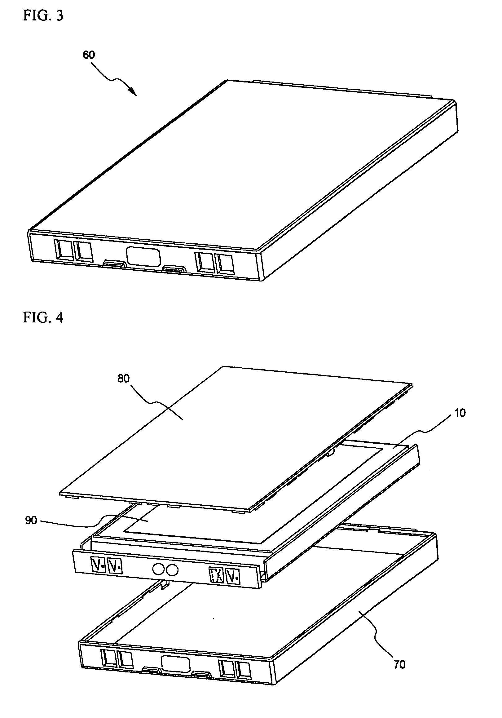
[0021] In the battery pack according to the present invention, the battery can be fixedly located in the pack case without using an ultrasonic welding method, and therefore, the size and the structure of the case are not particularly restricted. Also, the movement of the battery in the inner space of the case is restrained, and therefore, short circuit of the battery pack or suspension of power supply from the battery pack due to the external impacts is effectively prevented.
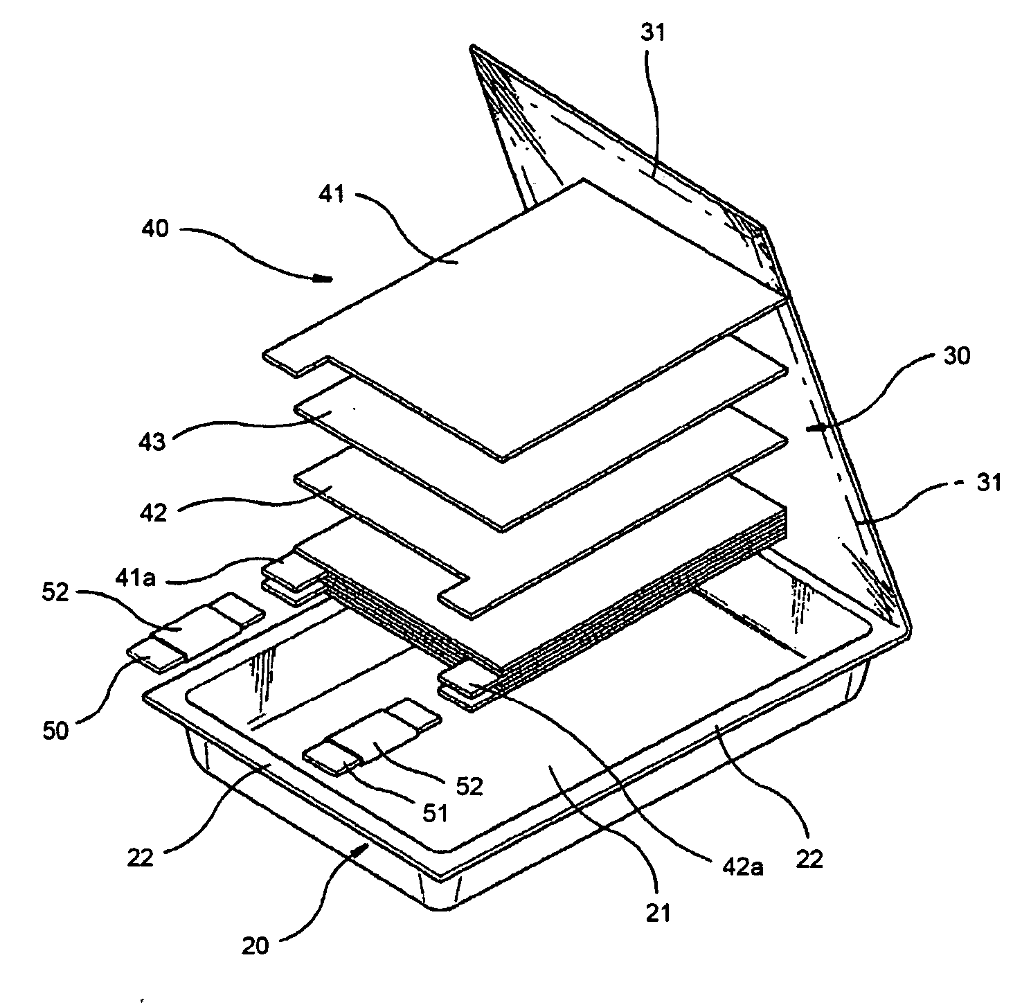
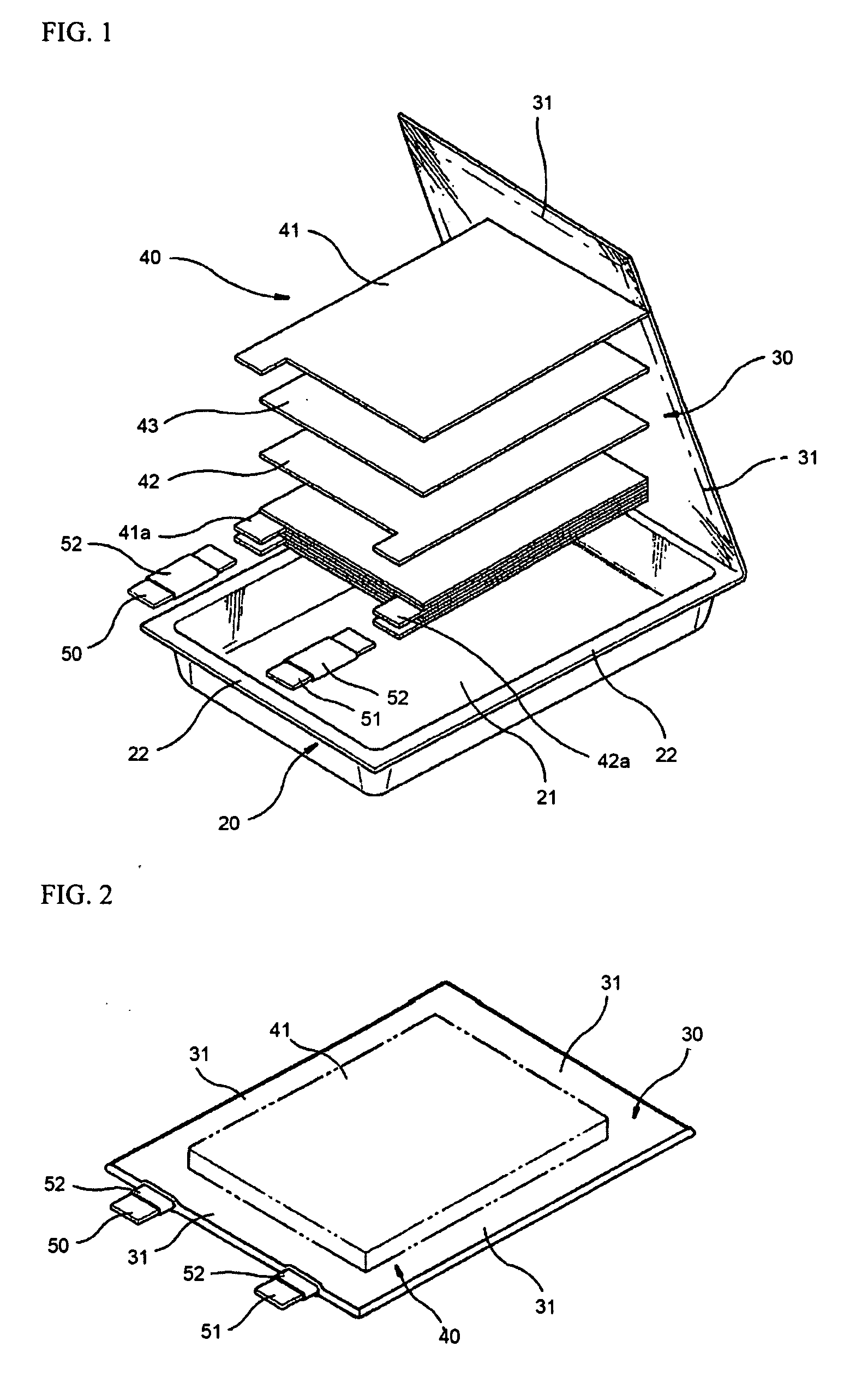
[0024] Preferably, the battery is a pouch-shaped battery, which can be manufactured to be light weight with small thickness although the mechanical strength of the pouch-shaped battery is low. More preferably, the battery is a lithium-ion polymer battery having low possibility of leakage of an electrolyte. When the pouch-shaped battery is located in the inner space of the pack case, an empty space is formed between the inner surface of the upper end of the pack case and the upper end of the pouch-shaped battery because of the construction of electrode terminals, a protection circuit module (PCM), and insulating members, which are mounted at or coupled to the upper end of the pouch-shaped battery. The upper end of the battery is relatively weak with the result that the upper end of the battery is easily deformed when the battery pack falls or the external impacts are applied to the battery pack, and therefore, defectiveness of the battery pack is caused. For example, when the battery is moved toward the upper end of the inner space of the pack case as the battery pack falls or the external impacts are applied to the battery pack, short circuit is caused due to the electrical contact between the components of the battery pack. On the other hand, when the battery is moved toward the lower end of the inner space of the pack case, the electrical connection between the components disposed at the upper end of the battery is broken.

Problems solved by technology

As a result, it is difficult to manufacture the case body and the upper cover by die casting and injection molding.
Furthermore, the welding strength is reduced, and therefore, poor welding rate is increased.
For this reason, the application of the case having a small thickness to the battery pack is restricted.

Method used


Image

  • Battery pack of improved stability
  • Battery pack of improved stability
  • Battery pack of improved stability

Examples


Embodiment Construction

[0045] Now, preferred embodiments of the present invention will be described in detail with reference to the accompanying drawings. It should be noted, however, that the scope of the present invention is not limited by the illustrated embodiments.

[0046] First, a process of manufacturing an exemplary pouch-shaped battery, which can be preferably used in a battery pack according to a preferred embodiment of the present invention will be described with reference to FIGS. 5 to 9.

[0047] Referring to FIG. 5, sealed outer edges 120 and 130 of a case, which are attached to each other by thermal welding in a state that an electrode assembly and an electrolyte are mounted in the battery pack, are bent upward. On the upper sealed outer edge 120 is, which is bent as described above, loaded a first insulating member 200, and a cathode terminal 140 and an anode terminal 150 are bent downward such that the cathode terminal 140 and the anode terminal 150 are placed on the first insulating member ...


PUM


Abstract

Disclosed herein is a battery pack wherein a rectangular battery having an electrode assembly and an electrolyte contained therein in a sealed state is received in a pack case, and an insulating material is filled in a space defined between the inner surface of the upper end of the pack case and the upper end of the battery, whereby the battery pack is manufactured with a reduced thickness, the assembly process of the battery pack is very simple, and short circuit of the battery pack or suspension of power supply from the battery pack, which may occur as the battery is moved, is effectively prevented even when the battery pack falls down or external impacts are applied to the battery pack.

Description

FIELD OF THE INVENTION [0001] The present invention relates to a battery pack having improved stability, and, more particularly, to a battery pack wherein a rectangular battery having an electrode assembly and an electrolyte contained therein in a sealed state is received in a pack case, and an insulating material is filled in a space defined between the inner surface of the upper end of the pack case and the upper end of the battery, whereby the battery pack is manufactured with a reduced thickness, the assembly process of the battery pack is very simple, and short circuit of the battery pack or suspension of power supply from the battery pack, which may occur as the battery is moved, is effectively prevented even when the battery pack falls down or external impacts are applied to the battery pack. BACKGROUND OF THE INVENTION [0002] As mobile devices have been increasingly developed, and the demand of such mobile devices has increased, the demand of secondary batteries has been als...

Claims


Application Information

Patent Timeline
IPC IPC(8): H01M2/02H01M10/05H01M50/211
CPCH01M2/105H01M2/1061H01M2/1094H01M10/052Y02E60/10H01M50/213H01M50/24H01M50/211H01M50/20Y02P70/50
Inventor MOON, KI EOBKIM
Owner LG ENERGY SOLUTION LTD
Learn More