Shielding base member and method of manufacturing the same
a technology of shielding base and base member, which is applied in the direction of electrical apparatus construction details, transportation and packaging, and association of printed circuit non-printed electric components, can solve the problems of difficult handling of metal foils that are patterned, and achieve the effects of low haze, high optical transmittance, and high opaqueness
- Summary
- Abstract
- Description
- Claims
- Application Information
AI Technical Summary
Benefits of technology
Problems solved by technology
Method used
Image
Examples
first embodiment
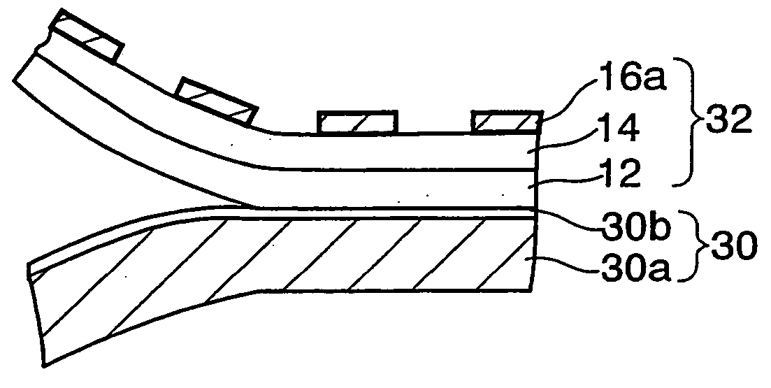
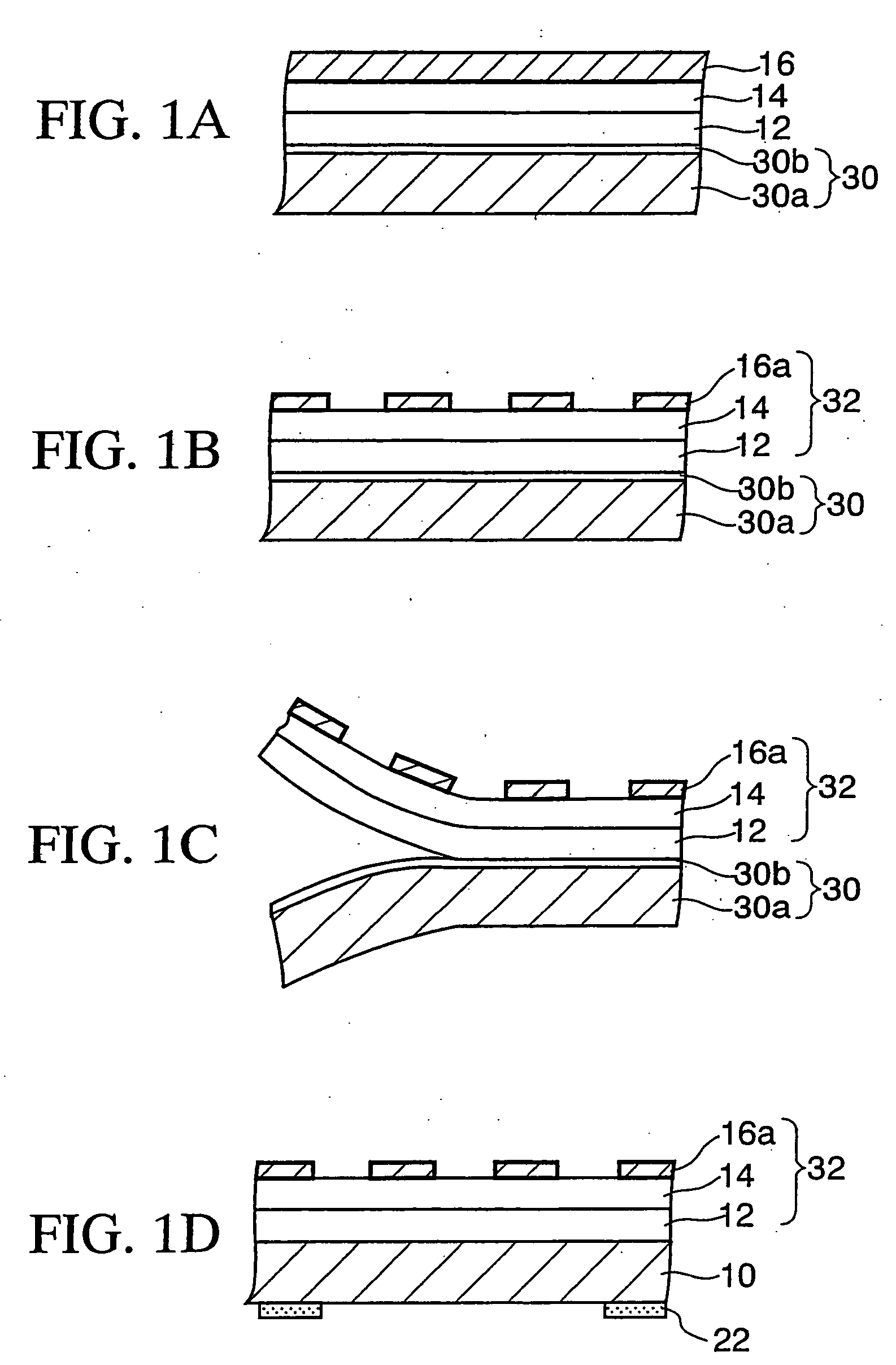
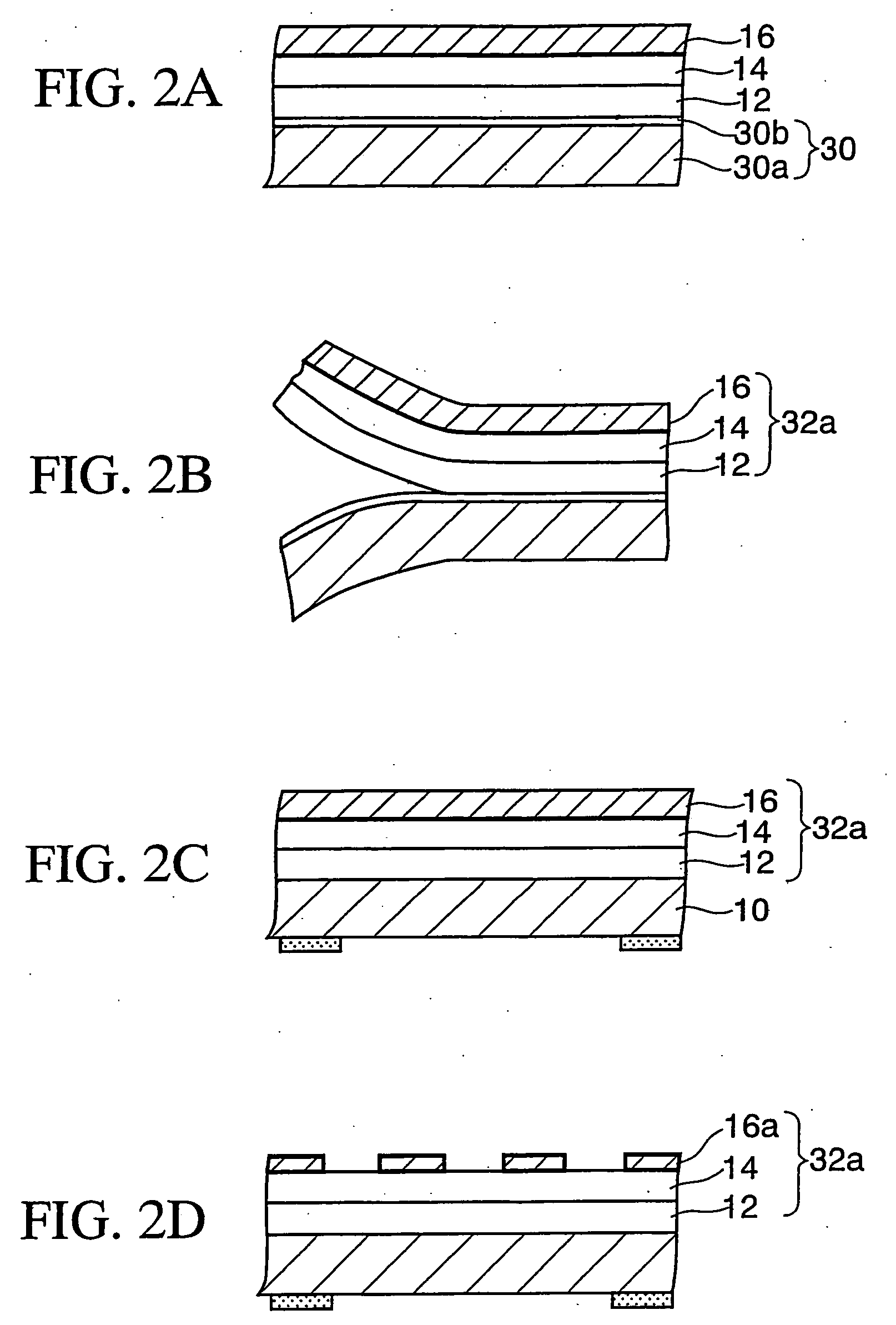
[0054] Manufacturing methods for producing the shielding base member according to the first embodiment of the present invention will first be described.
First Manufacturing Method
[0055] As shown in FIG. 1A, a PET (polyethylene terephthalate) film 30a is used as an example of the plastic film. A silicone layer 30b (release layer) of 1 μm, for example, is coated on one surface of this PET film 30a.
[0056] To form the silicone layer 30b a solution of 600 wt % in total is formed by mixing 100 parts by weight of the silicone (KS-3703 manufactured by Shin-Etsu Chemical Co., Ltd.), 1 part by weight of the catalyst (CAT-PL-50T), and 499 parts by weight of solvent (toluene). Then, the silicone layer 30b is formed by coating this solution on the PET film 30a by a bar coater, and then annealing at 120° C. for 30 seconds. This plastic film 30a on one surface of which the silicone layer 30b is formed is referred to as “separator 30” hereinafter.
[0057] Then, a first adhesive layer 12 having a ...
second embodiment
[0096]FIG. 4 is a schematic sectional view showing a shielding base member according to a second embodiment of the present invention. The shielding base member of the second embodiment differs from the shielding base member of the first embodiment in that it has no separate near-infrared absorbing layer and such function is given to the adhesive layer. Therefore, in FIG. 4, the same symbols are affixed to the same elements as those in FIG. 3A, and their detailed explanation will be omitted here.
[0097] As shown in FIG. 4, the shielding base member 26a of the second embodiment has a structure lacking a separate near-infrared absorbing layer. The copper layer pattern 16a is formed on the glass substrate 10 via the first adhesive layer 12 and the resin layer 14, and then the PET reflection preventing layer 20 is formed on the copper layer pattern 16a via the third adhesive layer 12b having the near-infrared absorbing function. In this manner, since the third adhesive layer 12b has the ...
third embodiment
[0102]FIG. 5 is a schematic sectional view showing a shielding base member according to a third embodiment of the present invention. The difference between the shielding base member of the third embodiment and the shielding base member of the first embodiment is that in the third embodiment the metal layer pattern of the shielding base member is formed on the surface of the transparent substrate on the PDP side and reflection preventing layers are formed on both surfaces of the transparent substrate. Therefore, in FIG. 5, the same symbols are affixed to the same elements as those in FIG. 3A, and their detailed explanation is omitted here.
[0103] As shown in FIG. 5, in the shielding base member 26b of the third embodiment, the black frame layer 22 is formed on one surface of the glass substrate 10, i.e., the surface on the PDP side, and the copper layer pattern 16a is formed on the black frame layer 22 and the glass substrate 10 via a first adhesive layer 12c and the resin layer 14. ...
PUM
| Property | Measurement | Unit |
|---|---|---|
| wavelength | aaaaa | aaaaa |
| thickness | aaaaa | aaaaa |
| thickness | aaaaa | aaaaa |
Abstract
Description
Claims
Application Information
 - R&D
- Intellectual Property
- Life Sciences
- Materials
- Tech Scout
- Unparalleled Data Quality
- Higher Quality Content
- 60% Fewer Hallucinations
Browse by: Latest US Patents, China's latest patents, Technical Efficacy Thesaurus, Application Domain, Technology Topic, Popular Technical Reports.
© 2025 PatSnap. All rights reserved.Legal|Privacy policy|Modern Slavery Act Transparency Statement|Sitemap|About US| Contact US: help@patsnap.com


