Riflescope with image stabilization

Active Publication Date: 2006-09-14
NOMIS
View PDF50 Cites 55 Cited by
  • Summary
  • Abstract
  • Description
  • Claims
  • Application Information

AI Technical Summary

Benefits of technology

[0007] The present invention overcomes the limitations of the prior art by providing an image stabilization or vibration reduction facility for a riflescope and firearm. The facility has a transparent optical element that refracts incoming rays passing based on motion, to provide a stabilized image, which is transmitted to a user along an optical path of a rifle scope. A feedback transducer connected an output signal from the stabilization facility indicates a characteristic of the output signal. The transducer may be a second reticle that moves based on motion of the riflescope to

Problems solved by technology

A significant limitation of shooting accuracy is presented by unsteadiness of the rifle.
However, most other shooters must content with imperfect supports for their rifles, with a standing shooter hand-holding a rifle being a relatively unstable condition for example.
With accurate rifles capable of accuracies of better than one minute of angle or about one inch per hundred yards, even slight movements of the rifle can lead to inaccuracies far in excess of the capability of the rifle.
Even a shift of only 0.01 inch by the muzzle of the rifle can generate such a significant inaccuracy.
Moreover, factors such as wind and the shooter's breathing and heartbeat can generate such devia

Method used


Image

  • Riflescope with image stabilization
  • Riflescope with image stabilization
  • Riflescope with image stabilization

Examples


Example

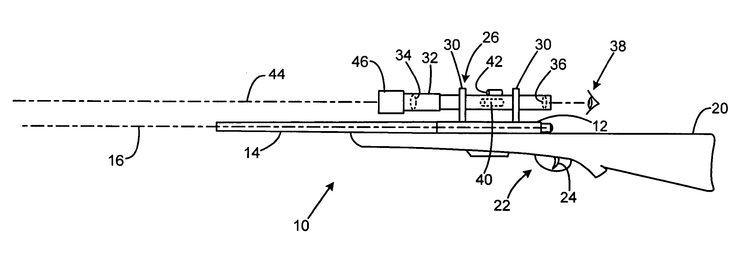
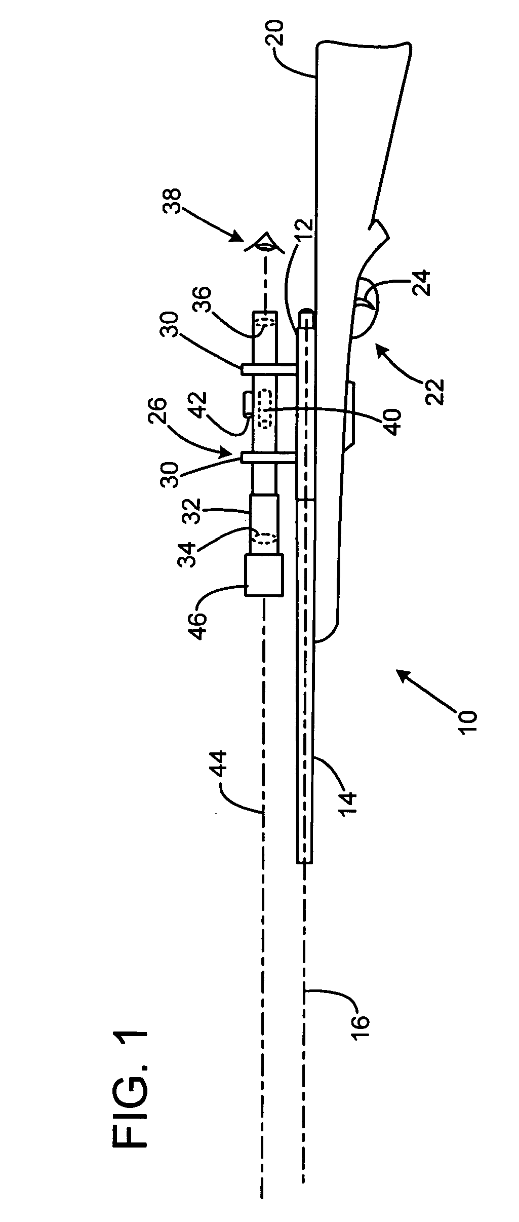
[0013]FIG. 1 shows a rifle 10 with a receiver 12 providing a frame, a barrel 14 connected to the receiver and defining a barrel axis 16. A stock 20 is connected to the receiver and partially encompasses a trigger mechanism 22, leaving exposed a trigger lever 24. A telescopic rifle sight or riflescope 26 is secured to the receiver by way of scope mounts 30. The scope has an elongated tubular housing 32 with an enlarged forward portion housing an objective lens 34, and a rear portion housing an eyepiece lens 36. (All lenses shown in simplified form instead of the preferred multiple element arrangements.) A user 38 views an image of an intended target from the rear of the eyepiece. A prismatic optical element 40 is positioned between the objective and eyepiece lenses, and is shifted vertically and horizontally by adjustment knobs 42 to shift the image to coincide with a bullet's expected point of impact, with adjustments for bullet drop based on distance, and for windage due to cross w...


PUM


Abstract

An image stabilization or vibration reduction facility for a riflescope and firearm has a transparent optical element that refracts incoming rays passing based on motion, to provide a stabilized image, which is transmitted to a user along an optical path of a rifle scope. A feedback transducer connected an output signal from the stabilization facility indicates a characteristic of the output signal. The transducer may be a second reticle that moves based on motion of the riflescope to indicate the degree of deflection by the stabilization facility, and may illuminate when the stabilization facility is in a neutral condition without deflection. The rifle may include a trigger block the prevents trigger operation until a neutral condition is detected. A rangefinder and wind indicator input may be provided, with the stabilization facility refracting the incoming image to compensate for bullet drop at the indicated distance, and for the effects of the indicated wind speed and direction; the riflescope may omit conventional bullet drop and windage adjustment elements.

Description

FIELD OF THE INVENTION [0001] This invention relates to riflescopes for firearms, and more particularly to image stabilization systems. BACKGROUND OF THE INVENTION [0002] Rifles used for precision long range shooting, whether for military, law enforcement, hunting, or target shooting, often employ high power telescopic sights or riflescopes that provide a magnified image of the target, with crosshairs or another reticle at the same focal distance as the image. Other than the reticle, the riflescope provides a clear optical path that provides the shooter with a much clearer image of the target area than does the naked eye. Such riflescopes are generally elongated and compact compared to the dimensions of the rifle, so that they do not add excessive bulk and weight to the rifle. For longer ranges, higher magnifications are often employed. [0003] A significant limitation of shooting accuracy is presented by unsteadiness of the rifle. Bench-rest competition shooters employ stable platfo...

Claims


Application Information

Patent Timeline
IPC IPC(8): G03B17/00G02B23/00F41G1/38
CPCF41C27/22F41G1/38F41G3/06F41G3/08G02B23/14G02B27/646
Inventor LOWREY, JOHN WILLIAM III
Owner NOMIS
Why Eureka
Try Eureka