Vibrating gyro element

Inactive Publication Date: 2006-09-14
SEIKO EPSON CORP
View PDF2 Cites 26 Cited by
  • Summary
  • Abstract
  • Description
  • Claims
  • Application Information

AI Technical Summary

Benefits of technology

[0025] The provision of a weight at the tip of each of the drive arms and the detection arms increases the mass of the drive arms so as to provide large Coriolis forces, and also increases strains arising in the detection arms. Furthermore, the provision of grooves in the driv

Problems solved by technology

However, in the vibrating gyro element with such a structure, since a Coriolis force is transmitted to the detection arm via the support arm and base portion, energy loss is large, which lowers the sensitivity of angular velocity detection.
In addition, the base portion for supporting the vibrating gyro element is tightly fixed, which causes a problem that the sensitivity of angular velocity detection is significantly lowered, since the bas

Method used


Image

  • Vibrating gyro element
  • Vibrating gyro element
  • Vibrating gyro element

Examples


first embodiment

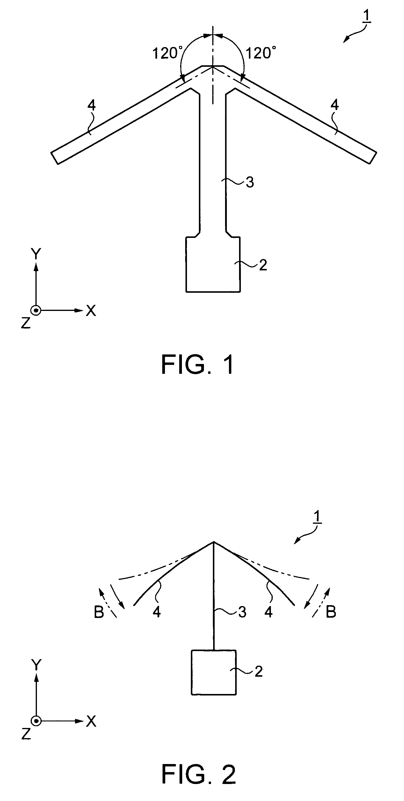
[0046]FIG. 1 is a plan view illustrating a vibrating gyro element according to a first embodiment of the invention.

[0047] A vibrating gyro element 1 is formed from a Z-cut plate of quartz by etching processing employing photolithography. The Z-cut plate is a quartz substrate of which thickness direction is the Z-axis direction and of which plane is parallel to the XY-plane.

[0048] The vibrating gyro element 1 includes a base portion 2, a detection arm 3 extending in the Y-axis direction from one side of the base portion 2, and a pair of drive arms 4 extending from the detection arm 3. One drive arm 4 extends in the direction at an angle of substantially +120 degrees with respect to the Y-axis direction. The other drive arm 4 extends in the direction at an angle of substantially −120 degrees with respect to the Y-axis direction. The extension directions of the drive arms 4 are designed to make an angle in the region of 120°±3° with the Y-axis in consideration of manufacturing variat...

second embodiment

[0060] A vibrating gyro element according to a second embodiment of the invention will be described.

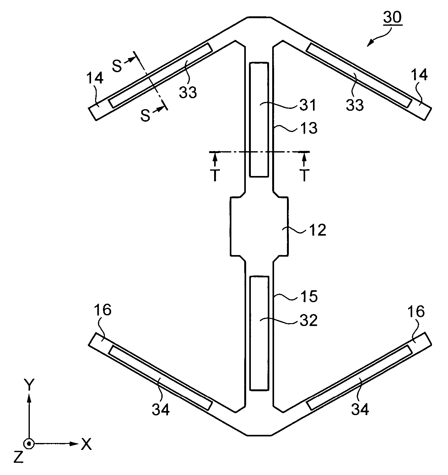
[0061]FIG. 4 is a plan view illustrating the structure of the vibrating gyro element.

[0062] A vibrating gyro element 10 is formed from quartz by etching processing employing photolithography

[0063] The vibrating gyro element 10 includes a base portion 12, detection arms 13 and 15 extending in the Y-axis direction from the both sides of the base portion 12, and pairs of drive arms 14 and 16 extending from the detection arms 13 and 15, respectively. The drive arms 14 extend in the directions at angles of substantially +120 and −120 degrees, respectively with respect to the Y-axis direction. The drive arms 16 also extend in the directions at angles of substantially +120 and −120 degrees, respectively, with respect to the Y-axis direction. The extension directions of the drive arms 14 and 16 are designed to make an angle in the region of 120°±3° with the Y-axis in consideration of manuf...


PUM


Abstract

A vibrating gyro element that is formed of a piezoelectric material having a trigonal crystal structure and having a trigonal axis with respect to the Y-axis, includes a base portion, a detection arm extending in the Y-axis direction from one side of the base portion, and a pair of drive arms extending from the detection arm. One of the pair of drive arms extends in a direction at an angle of substantially +120 degrees with respect to the Y-axis direction. The other of the pair of drive arms extends in a direction at an angle of substantially −120 degrees with respect to the Y-axis direction. The drive arms exist on substantially the same plane as the base portion and the detection arm.

Description

BACKGROUND [0001] 1. Technical Field [0002] The present invention relates to a vibrating gyro element that employs a piezoelectric material having a trigonal crystal structure. [0003] 2. Related Art [0004] In recent years, gyro sensors that detect angular velocity are frequently used for camera-shake correction in imaging apparatuses and position detection for automobiles and so forth by vehicle navigation systems employing GPS satellite signals. [0005] As a vibrating gyro element included in a gyro sensor, e.g. a so-called double T-shape vibrating gyro element is known in which substantially T-shape drive vibration systems are disposed symmetrically with respect to the center detection vibration systems (refer to JP-A-2004-245605, FIG. 1). In the double T-shape vibrating gyro element, a base portion is provided with substantially T-shape drive vibration systems including drive arms and support arms, and detection vibration systems including detection arms. A Coriolis force arising ...

Claims


Application Information

Patent Timeline
IPC IPC(8): G01P15/08G01C19/56G01C19/5621H01L41/08H01L41/18
CPCG01C19/5607G01C19/56
Inventor UNNO, YUKIHIRO
Owner SEIKO EPSON CORP
Why Eureka
Try Eureka