
R-t-b sintered magnet and rare earth alloy

Active Publication Date: 2006-09-14
HITACHI METALS LTD
View PDF17 Cites 19 Cited by
  • Summary
  • Abstract
  • Description
  • Claims
  • Application Information

AI Technical Summary

Benefits of technology

[0010] In order to overcome the problems described above, an object of the present invention is to provide an R-T-B based sintered magnet of which the remanence is increased by minimizing both the decrease in coercivity and the decrease in the volume percentage of its main phase.
[0021] According to the present invention, the abnormal grain growth can be suppressed without producing any boride phase. As a result, an R-T-B based sintered magnet can be obtained with the decreased in coercivity minimized and with the remanence increased.

Problems solved by technology

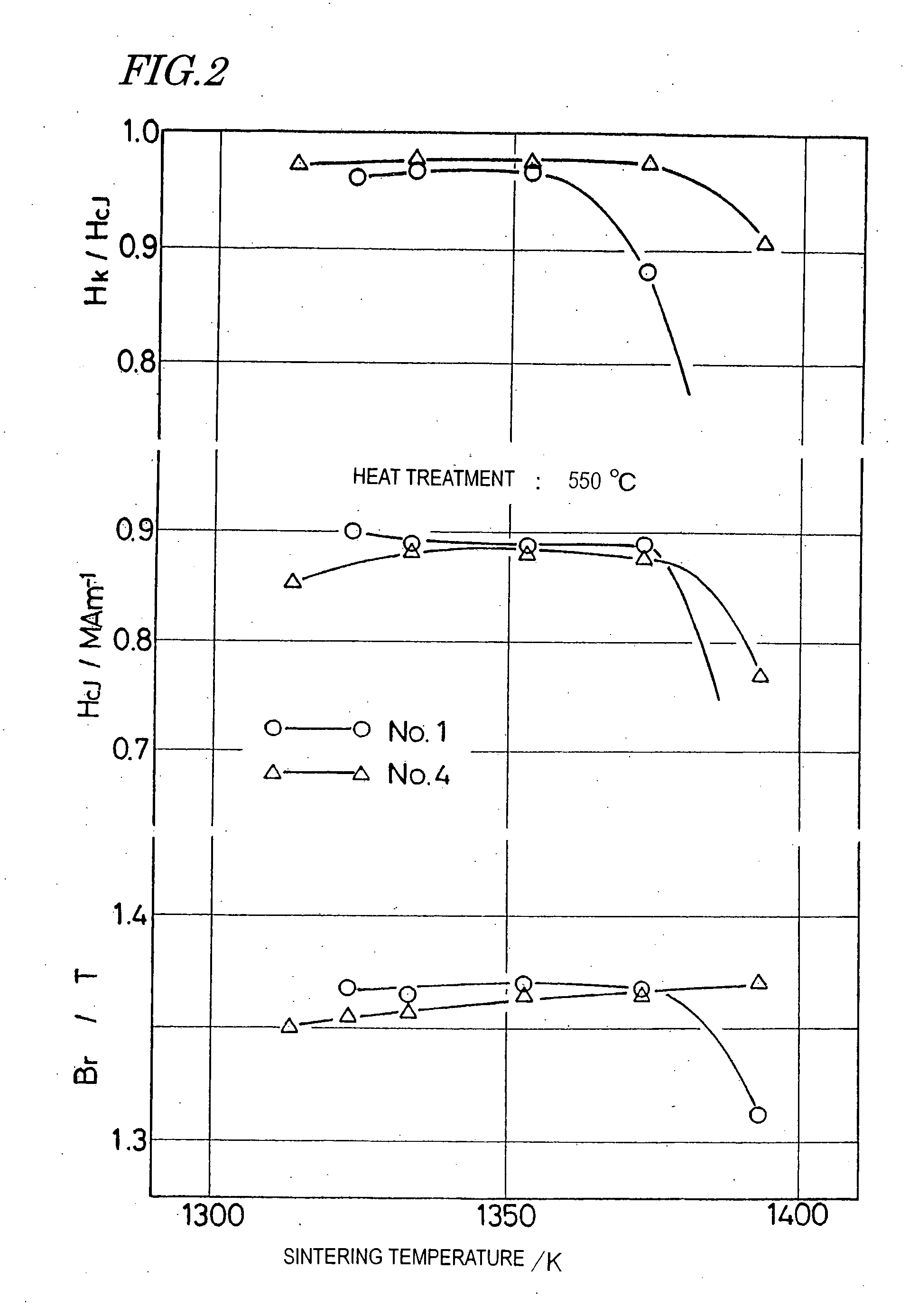
However, if the sintering process is carried out either at a higher temperature or for a longer time to increase the density of an R-T-B based sintered magnet, then the sintered density will increase but the crystal grains thereof will have excessively big sizes to cause a decrease in coercivity, which is a problem.
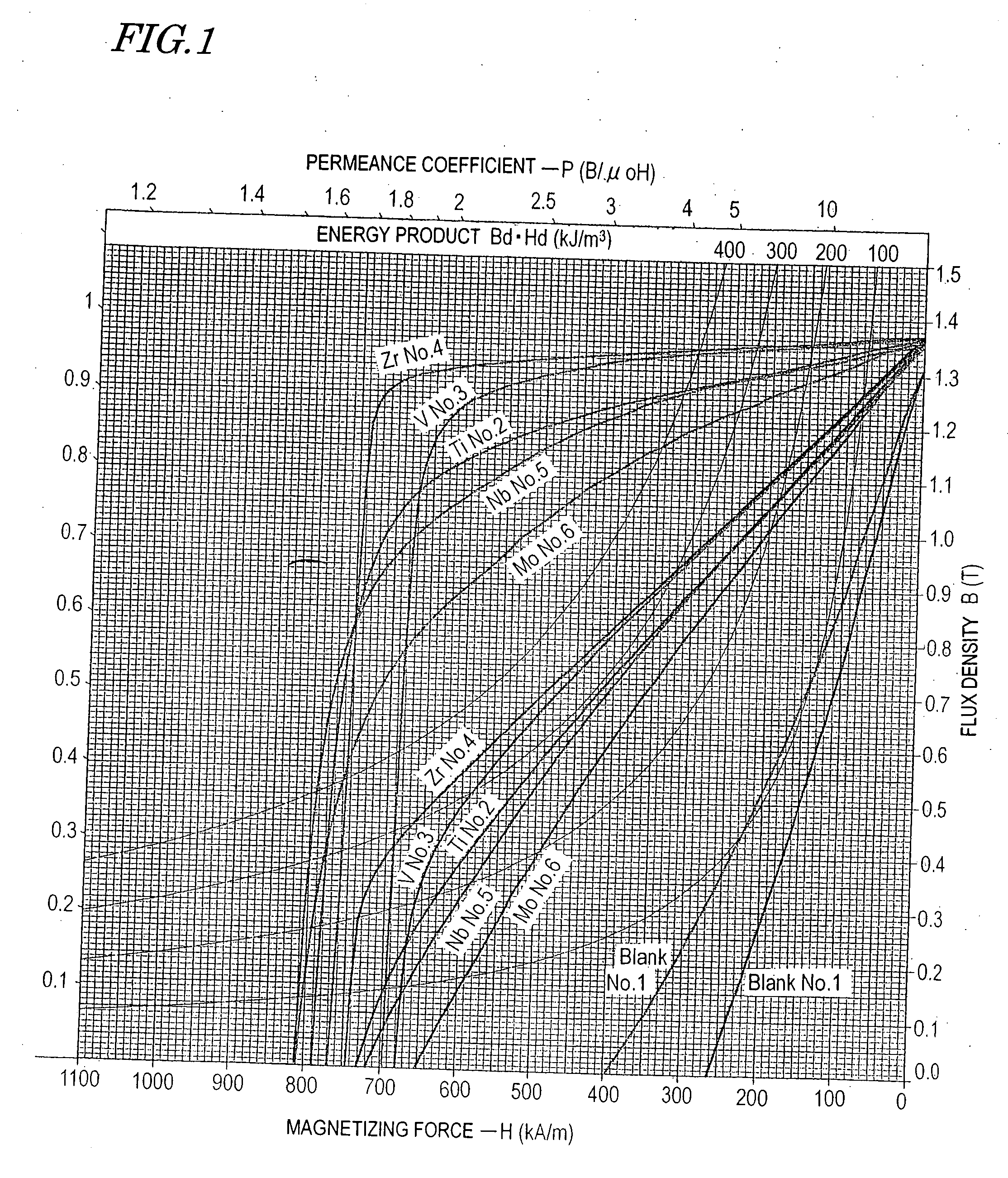
Particularly if an “abnormal grain growth” occurred to produce giant crystal grains (main phases) locally, then the square ratio Hk / HcJ of the demagnetization curve would decrease so much as to cause various inconveniences when such a magnet is actually used.
That is to say, in the prior art, it is difficult to increase the sintered density of an R-T-B based sintered magnet without sacrificing its coercivity.

Method used


Image

  • R-t-b sintered magnet and rare earth alloy
  • R-t-b sintered magnet and rare earth alloy
  • R-t-b sintered magnet and rare earth alloy

Examples


experimental example no.1

EXPERIMENTAL EXAMPLE NO. 1

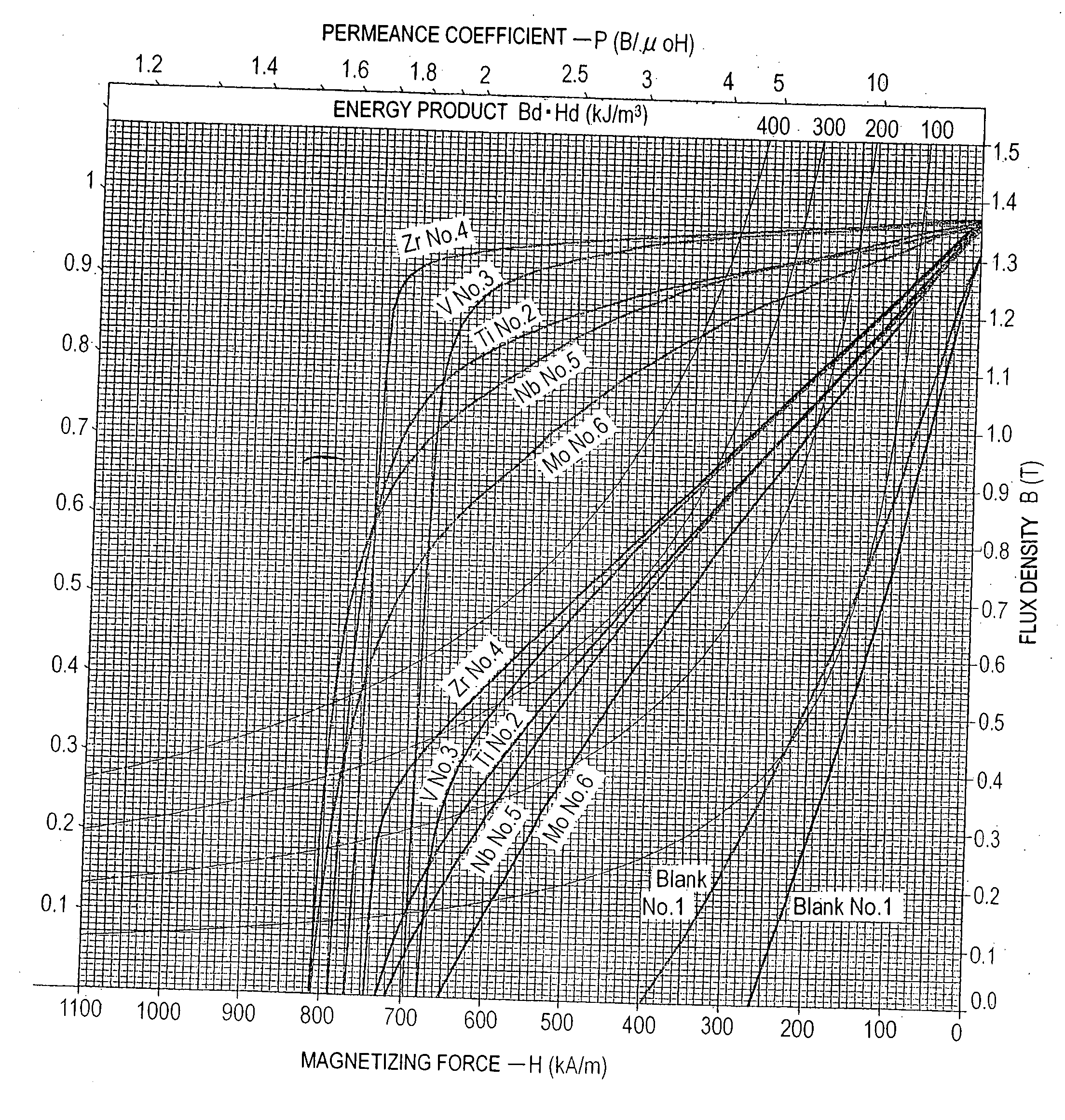
[0058] Magnets having the compositions shown in Table 1 were made in the following manner as Samples Nos. 1 through 6, respectively. It should be noted that the compositions shown in Table 1 are values obtained by analyzing the resultant sintered magnets, not the compositions of the mother alloys. The composition analysis was carried out by a known method using an ICP produced by Shimadzu Corporation and a gas analyzer produced by Horiba, Ltd.

[0059] In Table 1, Fe is shown as the balance. Actually, however, the balance includes Fe and very small amounts of inevitably contained impurities. The same statement will apply to Table 3 to be mentioned later.

[0060] In each of the samples representing this experimental example, the mass fraction of B substantially agrees with its stoichiometric ratio defined with respect to the mass fractions of R and T. Also, calculating the volume percentages of the respective phases with the additive element M taken out of cons...

experimental example no.2

EXPERIMENTAL EXAMPLE NO. 2

[0081] Magnets having the compositions shown in the following Table 3 were produced by the same method as that used in Experimental Example No. 1. In this example, however, the concentration of oxygen in the atmospheric gas was controlled to 50 ppm or less in the fine pulverization process in order to reduce the content of oxygen in the resultant sintered magnet. These samples Nos. 7 through 20 prepared in this manner were sintered at various sintering temperatures, thereby obtaining sintered magnets, of which the properties were evaluated as shown in the following Table 4. In Table 4, each item was evaluated as in Experimental Example No. 1 described above.

TABLE 3SampleNdFeCoAlCuZrGaBOCNNo. 729.3Bal.0.880.160.09——1.020.220.060.011No. 829.4Bal.0.870.150.10——0.980.210.050.010No. 929.2Bal.0.880.150.09——0.960.220.060.010No. 1029.2Bal.0.880.160.09——0.940.220.060.011No. 1129.2Bal.0.890.160.10——0.900.210.070.010No. 1229.3Bal.0.870.160.100.10—1.020.220.060.011No...

experimental example no.3

EXPERIMENTAL EXAMPLE NO. 3

[0092] Sintered magnets, having a composition consisting of 22.0 mass % of Nd, 6.2 mass % of Pr, 2.0 mass % of Dy, 1.8 mass % of Co, 0.10 mass % of Cu, 0.94 mass % of B, 0.05 mass % of Ga, X (0 to 4) mass % of Zr, and Fe and inevitably contained impurities as the balance, were produced at various sintering temperatures by the same method as that adopted in Experimental Example No. 1 and the magnetic properties thereof were evaluated. The sintered magnets produced in this Experimental Example No. 3 had an oxygen content of 0.38 mass % to 0.41 mass %.

[0093]FIG. 16 is a graph showing how the magnetic properties changed with the mass fraction of Zr in two situations where the sintering temperatures were 1,060° C. and 1,080° C., respectively. In FIG. 16, the abscissa represents the Zr mass fraction, while the ordinate represents Hk (which is the strength of an external magnetic field when the magnetization becomes 90% of the remanence Br), coercivity HcJ and re...


PUM

PropertyMeasurementUnit
Percent by massaaaaaaaaaa

Abstract

A rare-earth sintered magnet according to the present invention, of which the main phase is an R2T14B type compound phase, includes: 27 mass % through 32 mass % of R, which is at least one rare-earth element that is selected from the group consisting of Nd, Pr, Tb, and Dy and that always includes at least one of Nd and Pr; 60 mass % through 73 mass % of T, which is either Fe alone or a mixture of Fe and Co; 0.85 mass % through 0.98 mass % of Q, which is either B alone or a mixture of B and C and which is converted-into B on a number of atoms basis when its mass percentage is calculated; more than 0 mass % through 0.3 mass % of Zr; at most 2.0 mass % of an additive element M, which is at least one element selected from the group consisting of Al, Cu, Ga, In and Sn; and inevitably contained impurities.

Description

BACKGROUND OF THE INVENTION [0001] 1. Field of the Invention [0002] The present invention relates to an R-T-B based sintered magnet and a rare-earth alloy as its material. [0003] 2. Description of the Related Art [0004] An R-T-B based sintered magnet, one of the most prominent high-performance permanent magnets (which is sometimes called a “neodymium-iron-boron-based sintered magnet”), has excellent magnetic properties, and is used in motors, actuators, and various other applications. [0005] An R-T-B based sintered magnet is comprised of a main phase consisting essentially of a compound with an R2Fe14B type crystal structure (i.e., R2Fe14B compound phase), an R-rich phase and a B-rich phase. Basic compositions of R-T-B based sintered magnets are disclosed, for example, in U.S. Pat. Nos. 4,770,723 and 4,792,368, the entire disclosures of which are hereby incorporated by reference. An R-T-B based sintered magnet has a higher maximum energy product than any of various other magnets, bu...

Claims


Application Information

Patent Timeline
IPC IPC(8): H01F1/057
CPCB22F2003/248B22F2998/00H01F1/058H01F1/0577C22C2202/02C22C38/16C22C38/10C22C38/06C22C38/005C22C33/0278B22F2998/10B22F3/02B22F2202/05B22F9/08B22F9/023B22F9/04B22F3/10B22F3/24
Inventor TOMIZAWA, HIROYUKIMATSUURA, YUTAKA
Owner HITACHI METALS LTD
Learn More