

Heat exchanger with beveled header
a heat exchanger and header technology, applied in the field of heat exchangers, can solve the problems of corroding chemicals to the engine, significant damage to the engine, and debris in ambient water, so as to reduce the flow of ambient water, reduce the dead spots, and reduce the effect of heat transfer capability
- Summary
- Abstract
- Description
- Claims
- Application Information
AI Technical Summary
Benefits of technology
Problems solved by technology
Method used
Image

Examples
Embodiment Construction
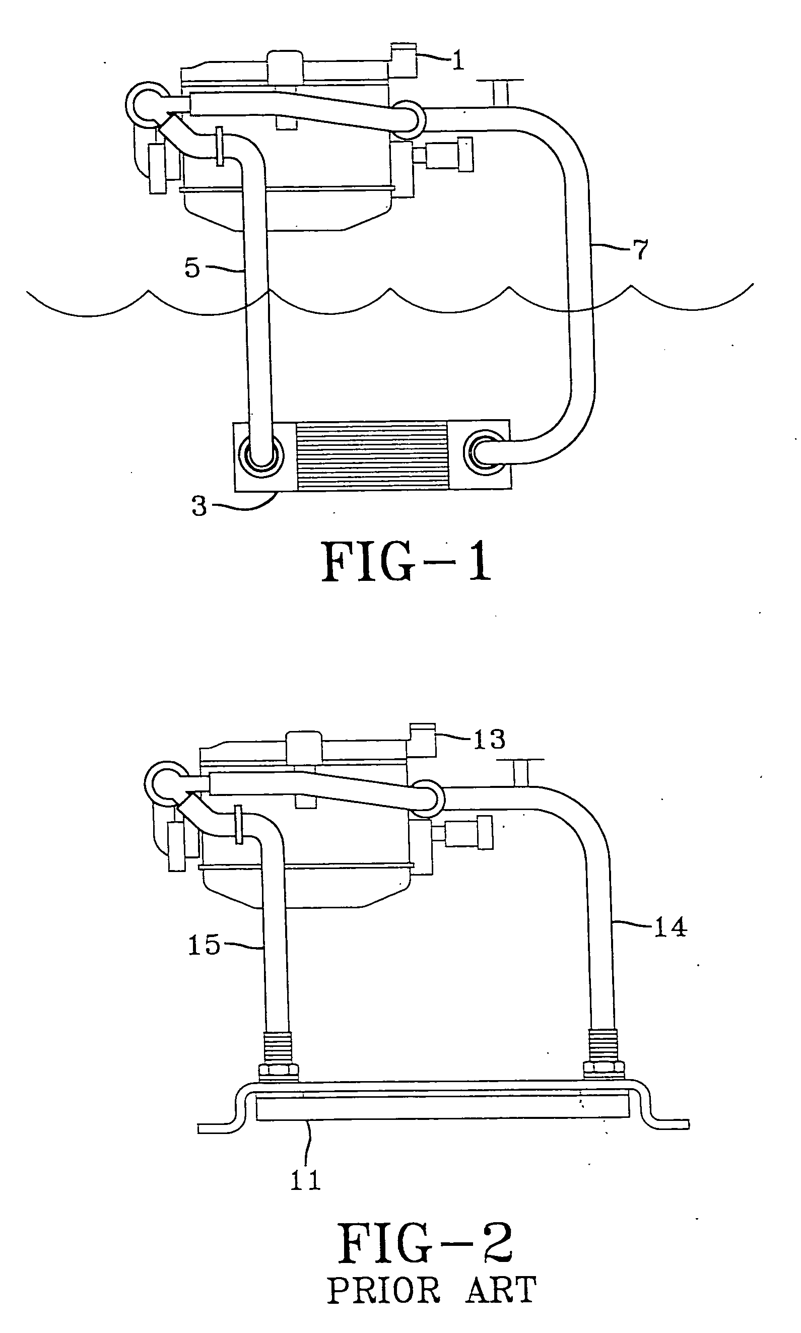
[0061] The fundamental components of a heat exchanger system for a water-going vessel are shown in FIG. 1. The system includes a heat source 1, a heat exchanger 3, a pipe 5 for conveying the hot coolant from heat source 1 to heat exchanger 3, and a pipe 7 for conveying cooled coolant from heat exchanger 3 to heat source 1. Heat source 1 could be an engine, a generator or other heat source for the vessel. Heat exchanger 3 could be a one-piece keel cooler (since only one-piece keel coolers are discussed herein, they are generally only referred to herein as “keel coolers.”) Heat exchanger 3 is located in the ambient water, below the water line (i.e. below the aerated water line), and heat from the hot coolant is transferred through the walls of heat exchanger 3 and expelled into the cooler ambient water.
[0062]FIG. 2 shows a heat exchanger 11 mounted on a vessel, for transferring heat from the coolant flowing from an engine or other heat source 13 to the ambient water. Coolant flows fr...
PUM
 Abstract
Description
Claims
Application Information