
Integrated circuit card and a method for manufacturing the same

Inactive Publication Date: 2006-09-14
RENESAS TECH CORP
View PDF0 Cites 24 Cited by
  • Summary
  • Abstract
  • Description
  • Claims
  • Application Information

AI Technical Summary

Benefits of technology

[0008] An IC card can be formed by bonding and uniting two members which are a semiconductor device and a case which carries the semiconductor device thereon, the semiconductor device comprising a wiring substrate and a semiconductor chip mounted and molded thereon. The case can be formed, for example, by an injection molding method using a thermosetting resin material and thus the case can be formed relatively inexpensively. On the other hand, the semiconductor device formed by mounting and molding a semiconductor chip on a wiring substrate is apt to be high in its manufacturing cost, but by making the size of the semiconductor device smaller than that of the IC card, it is possible to increase the number of semiconductor devices capable of being produced from a single wiring substrate and hence possible to decrease the semiconductor device manufacturing cost. By bonding the semiconductor device in question to an inexpensive case larger than the semiconductor device and which substantially defines the outline of the IC card to form the same card, it is possible to reduce the IC card manufacturing cost.
[0010] However, since it takes times for a bonding material to cure, if the semiconductor device moves from the case during curing (before completion of the curing) of the bonding material after the semiconductor device is mounted on the case through the bonding material, there is a possibility that the final IC card thickness after curing of the bonding material may become deviated from its standard value. It is necessary that the IC card deviated from its standard value of thickness be sorted as a defective card and removed. This leads to a lowering of the IC card production yield.
[0013] It is an object of the present invention to provide a technique able to improve the IC card production yield.
[0023] As an effect obtained by the typical modes of the present invention as disclosed herein, the production yield of the semiconductor device can be improved.

Problems solved by technology

If the IC card is thicker than its standard value, then at the time of inserting or pulling out the IC card into or from a slot, there is a possibility that a coating such as Au plating formed on an electrode surface within the slot may be damaged.
However, since it takes times for a bonding material to cure, if the semiconductor device moves from the case during curing (before completion of the curing) of the bonding material after the semiconductor device is mounted on the case through the bonding material, there is a possibility that the final IC card thickness after curing of the bonding material may become deviated from its standard value.
This leads to a lowering of the IC card production yield.

Method used


Image

  • Integrated circuit card and a method for manufacturing the same
  • Integrated circuit card and a method for manufacturing the same
  • Integrated circuit card and a method for manufacturing the same

Examples


first embodiment

[0096] An IC card and a manufacturing process for the same card according to this first embodiment will be described below with reference to drawings.

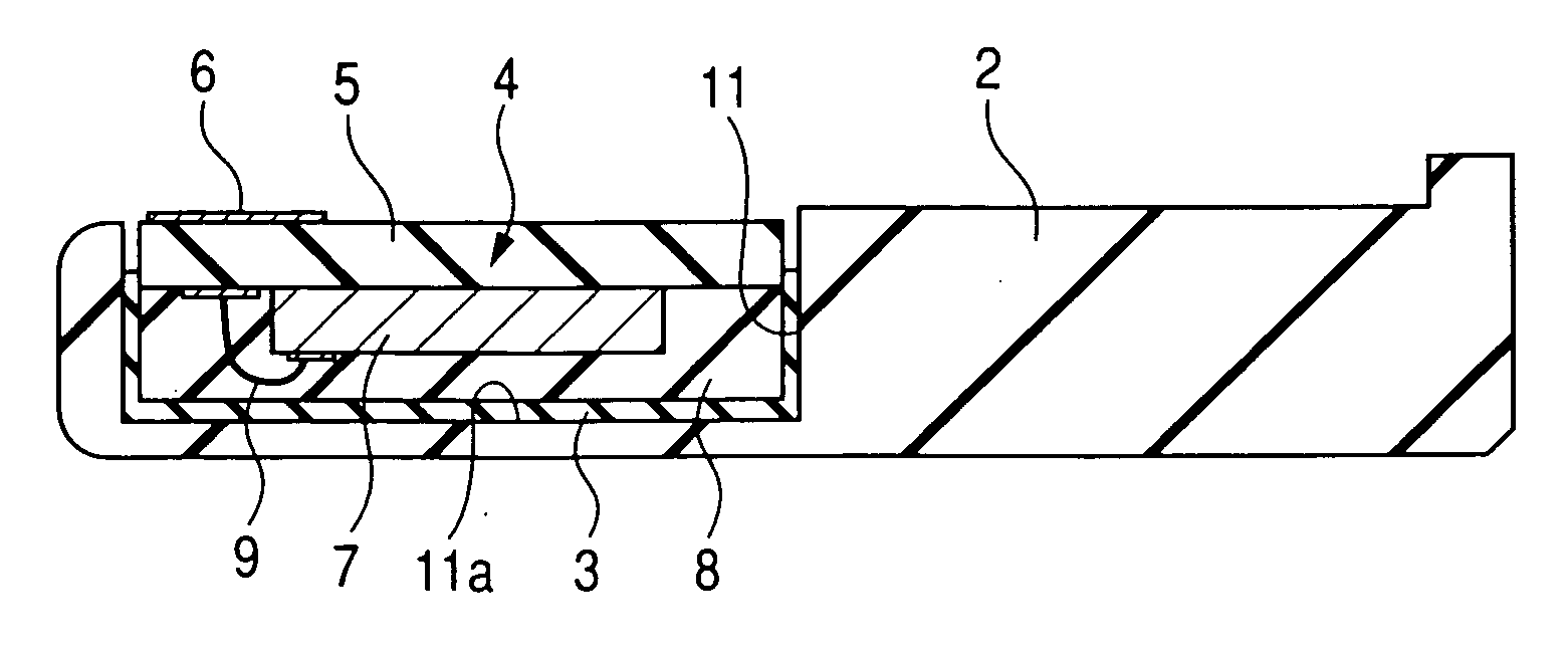
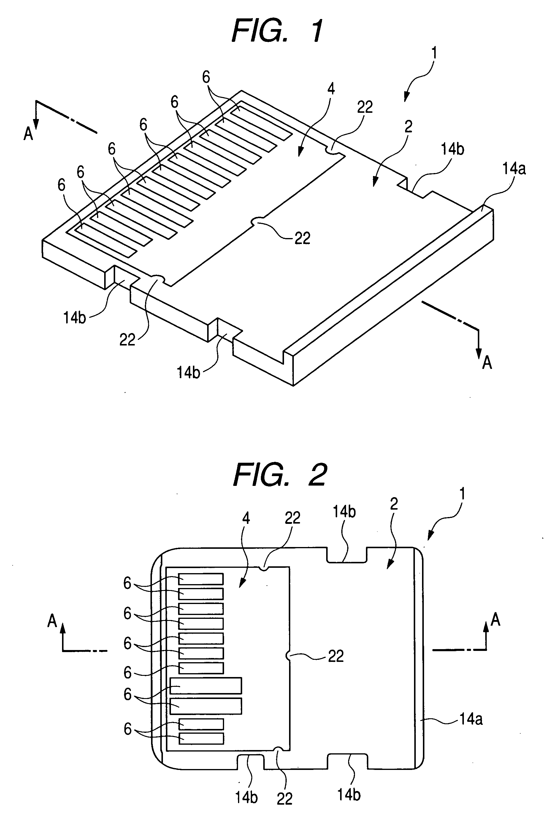
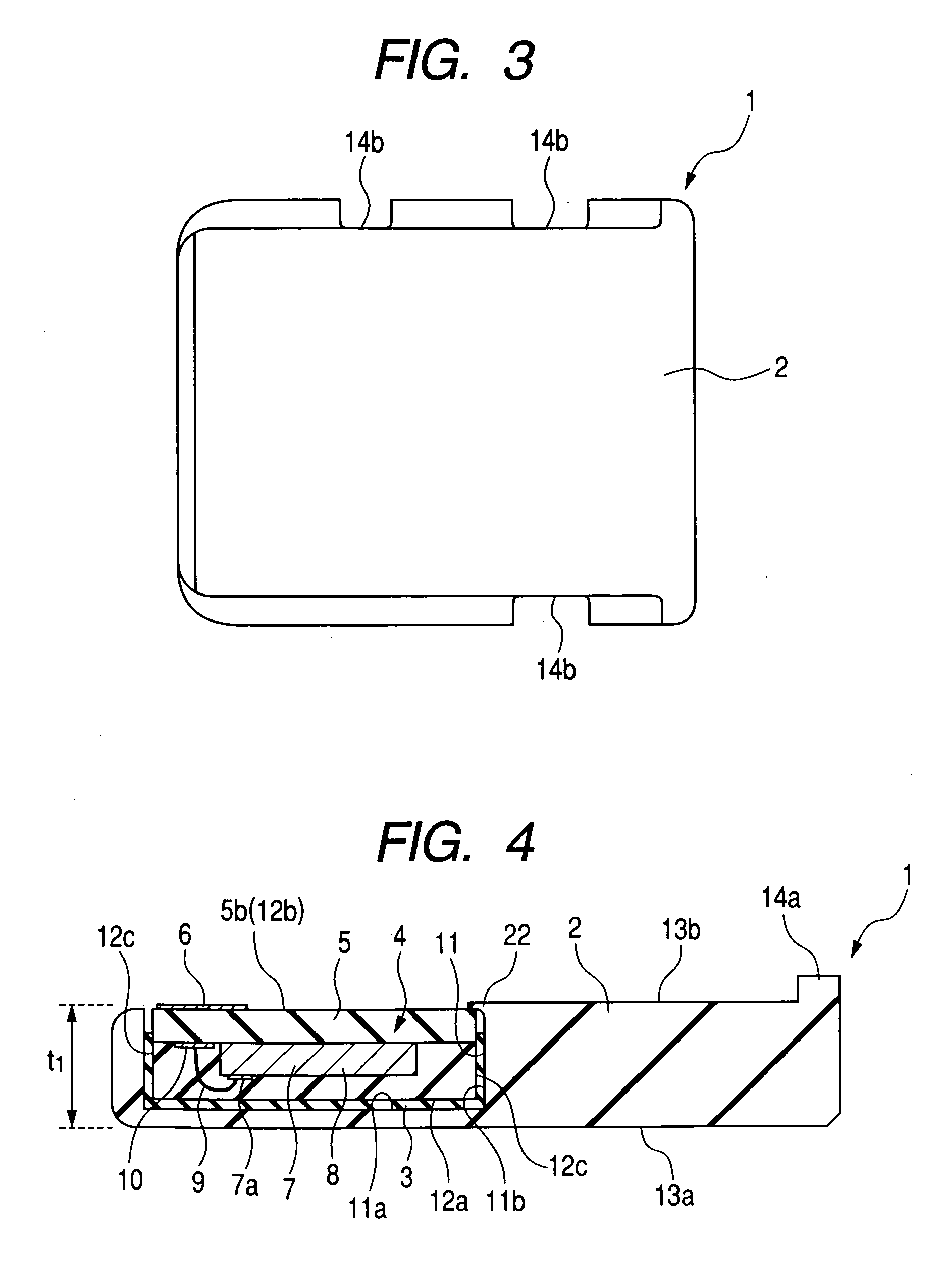
[0097]FIG. 1 is a perspective view showing an appearance of an IC card according to this first embodiment, FIG. 2 is a back view (underside view, bottom view, or plan view) of the IC card 1, FIG. 3 is a top view (surface view or plan view) of the IC card 1, and FIG. 4 is a sectional view (sectional side view) taken in a longitudinal direction (line A-A) of the IC card 1.

[0098] The IC card 1 of this embodiment shown in FIGS. 1 to 4 is a memory card employable mainly as an auxiliary device in any of various portable electronic devices, including for example information processors such as portable computers, image processors such as digital cameras, and communication devices such as smart phones and portable telephones. It can be loaded to any of these electronic devices. The IC card is in the shape of, for example, a small thin plate (...

second embodiment

[0147]FIG. 25 is a back view (bottom view, underside view, or plan view) of a case 2a used in manufacturing an IC card 1a according to this second embodiment and FIG. 26 is a sectional view taken on line D-D of the case 2a of FIG. 25. FIGS. 25 and 26 correspond substantially to FIGS. 14 and 15, respectively, in the previous first embodiment. Further, FIGS. 27 to 30 are sectional views of the IC card 1a in manufacturing steps, showing the same region as in FIG. 26. FIGS. 27 to 30 correspond substantially to FIGS. 16 to 19, respectively, in the previous first embodiment.

[0148] Also in this second embodiment, an IC body 4 is provided in the same way as in the first embodiment. Then, as shown in FIGS. 25 and 26, there is provided a case 2a used in manufacturing the IC card 1a of this embodiment. A manufacturing process for the case 2a may be performed before, after or simultaneously with the manufacturing process for the IC body 4.

[0149] The case 2a used in manufacturing the IC card 1...

third embodiment

[0155]FIG. 31 is a perspective view showing an appearance of a case 2b used in manufacturing an IC card 1b according to a third embodiment of the present invention, FIG. 32 is a back view (bottom view, underside view, or plan view) of the case 2b of FIG. 31, and FIG. 33 is a sectional view taken on line E-E of the case 2b of FIGS. 31 and 32. FIGS. 31 to 33 correspond substantially to FIGS. 13 to 15, respectively. FIGS. 34 to 37 are sectional views of the IC card 1b in manufacturing steps, showing the same region as FIG. 33. FIGS. 34 to 37 correspond substantially to FIGS. 16 to 19, respectively. FIG. 38 is a sectional view showing a comparative IC card 102.

[0156] Also in this third embodiment there is provided an IC body 4 in the same way as in the first embodiment. Then, as shown in FIGS. 31 to 33, there is provided a case 2b used in manufacturing the IC card 1b of this embodiment. A manufacturing process for the case 2b may be performed before, after or simultaneously with the ma...


PUM


Abstract

A semiconductor chip is mounted onto a wiring substrate having external connecting terminals, electrodes on the semiconductor chip and wiring lines on the wiring substrate are connected together electrically through bonding wires, and a sealing portion is formed by resin molding, to form an IC body. Further, a case formed of a thermoplastic resin is provided. The IC body is mounted into a recess of the case through a bonding material. Thereafter, a region near the recess of the case is deformed plastically to fix the IC body to the case and then the bonding material is cured. In this way there is fabricated an IC card comprising the case and the IC body whose stability is improved by being bonded to the case through the bonding material. The production yield of the IC card can be improved.

Description

CROSS-REFERENCE TO RELATED APPLICATION [0001] The present application claims priority from Japanese patent application No. 2005-070640 filed on Mar. 14, 2005, the content of which is hereby incorporated by reference into this application. BACKGROUND OF THE INVENION [0002] The present invention relates to an IC (Integrated Circuit) card manufacturing technique and an IC card, and more particularly to a technique applicable effectively to, for example, a semiconductor memory card (hereinafter referred to simply as “memory card”) and a technique for manufacturing the same. [0003] Among various IC cards which are in use, semiconductor memory cards (simply as “memory cards” hereinafter) such as a multi-media card (there is a standard established by Multi-Media Card Association) and an SD memory card (there is a standard established by SD Card Association) are a kind of a storage device which stores information in a semiconductor memory chip mounted therein. According to this storage devi...

Claims


Application Information

Patent Timeline
IPC IPC(8): G06K19/06H01L23/02
CPCG06K19/072G06K19/07732G06K19/07743H01L21/52H01L21/561H01L23/3121H01L23/49855H01L24/97H01L25/0657H01L2224/48091H01L2224/48227H01L2224/97H01L2225/06562H01L2924/01002H01L2924/01078H01L2924/01079H01L2924/14H01L2924/1815H01L2924/30105H01L2924/3025H01L2224/85H01L2924/00014H01L24/48H01L2924/01005H01L2924/01006H01L2924/01033H01L2224/451H01L2224/45144H01L2924/181H01L24/45H01L2924/00H01L2224/05599H01L2924/00012
Inventor HISHIZAWA, HIROTAKAOSAWA, KENJIOSAKO, JUNICHIROWADA, TAMAKI
Owner RENESAS TECH CORP
Learn More