Apparatus and method for beam drift compensation

a beam drift compensation and apparatus technology, applied in the direction of catching/draught deflectors, instruments, manufacturing tools, etc., can solve the problems of complex and expensive electro-optic devices, techniques, and high cost, and achieve limited effectiveness and high cost

Inactive Publication Date: 2006-09-14
HITACHI SEIKO LTD
View PDF7 Cites 55 Cited by
  • Summary
  • Abstract
  • Description
  • Claims
  • Application Information

AI Technical Summary

Problems solved by technology

Any difference between the detected position and the anticipated or desired position are corrected using compl...

Method used


Image

  • Apparatus and method for beam drift compensation
  • Apparatus and method for beam drift compensation
  • Apparatus and method for beam drift compensation

Examples


Embodiment Construction

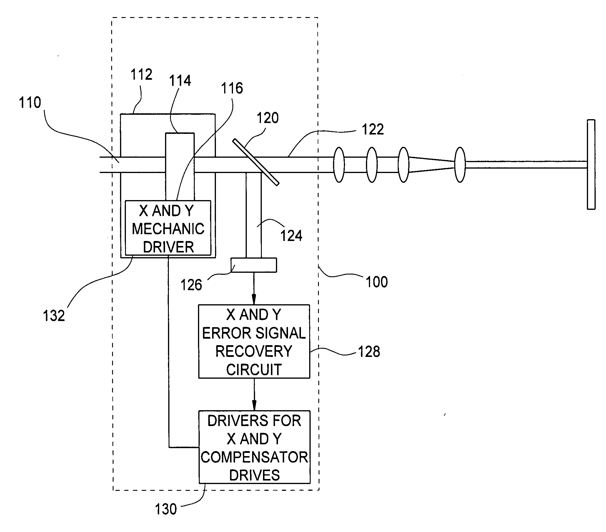
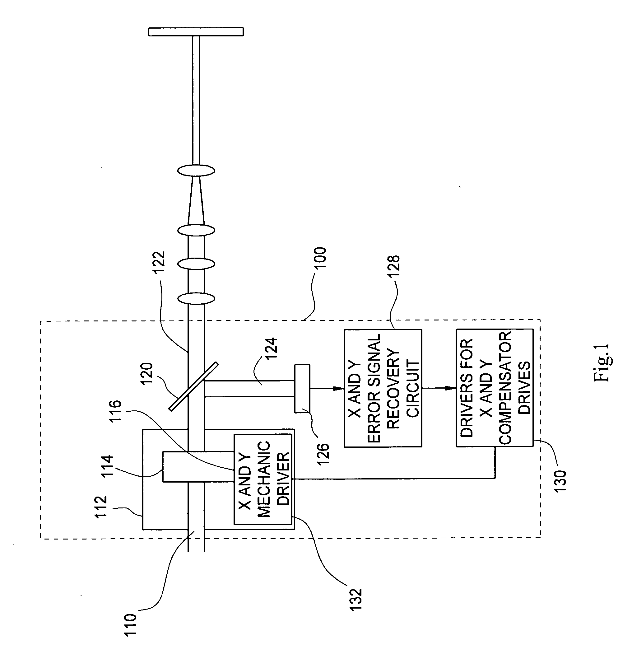
[0021] Referring now to FIG. 1, there is shown a first embodiment of a beam stabilizing system 100 used to monitor and adjust the position of a laser beam 110. The depicted embodiment includes a beam drift compensator 112 employing prismatic wedges 114 and 116 and a beam splitter 120. The beam splitter 120 may be e.g., a folding beam splitter mirror, a diffractive optical sampler, etc., which transmits a portion 122 of the incident beam 110 and reflects a portion 124 to position-sensing photosensor or photo imager 126.

[0022] It will be recognized that, as an alternative to the photo-sensitive detectors described herein, a position-sensing thermal device for sensing the heating effect of the incident beam, such as a thermal detector, pyroelectric device, thermopile sensors, or the like, may be employed in place thereof. Exemplary beam-compensating systems employing thermal sensors are described in detail below.

[0023] Although the laser source emission will be primarily referred to ...


PUM

PropertyMeasurementUnit
Refractionaaaaaaaaaa
Thermal propertiesaaaaaaaaaa
Optical propertiesaaaaaaaaaa

Abstract

An apparatus and method for maintaining a desired position of a collimated light beam are provided. An optical system includes one or more passive optical elements movably positioned in the beam path. Beam position is responsive to movement of at least one of the passive optical elements. The actual position of the beam is detected and compared with the desired beam position. An error signal is generated and the beam path is altered responsive to movement of one or more of the passive optical elements. In further aspects, beam shaping optics, such diffractive optics, are provided to shape the sensed beam portion. In still other aspects, thermal conditions of the laser may be monitored and a thermal map is provided to automatically compensate for estimated beam drift due to thermal conditions.

Description

BACKGROUND OF THE INVENTION [0001] The present invention relates an optical beam drift compensation apparatus and method for monitoring a beam position and optically compensating for changes in position of the beam so as to direct the laser beam along a desired optical path. The invention finds particular utility in connection with all manner of laser beam applications wherein a laser beam is delivered to a workpiece or other target to be processed, including industrial and other laser applications. Exemplary applications include laser machining, drilling, ablation, and so forth, illumination, photobonding or photocuring applications, and other laser processing applications. It will be recognized that the present invention may be employed with all manner of optical systems wherein it is necessary or desired to deliver a laser or other collimated ray path to a precise target location or otherwise maintain a precise propagation path. [0002] The direction or position of a laser beam te...

Claims


Application Information

Patent Timeline
IPC IPC(8): H01J40/14
CPCB23K26/04B23K26/422G01S5/16H04N1/047B23K26/043B23K26/702E06B7/26E06B3/4609
Inventor LIZOTTE, TODD E.OHAR, OREST P.
Owner HITACHI SEIKO LTD
Why Eureka
Try Eureka