Synchronous motor and electric driving system

a technology of synchronous motors and electric driving systems, applied in the direction of electric energy management, electric devices, magnetic circuits, etc., can solve the problems of difficult application to larger-sized cars beyond the 1-liter class, and achieve the effect of low vibration

Inactive Publication Date: 2006-09-14
HITACHI LTD
View PDF5 Cites 44 Cited by
  • Summary
  • Abstract
  • Description
  • Claims
  • Application Information

AI Technical Summary

Benefits of technology

[0021] According to the present invention, the synchronous motor with low vibrations can be obtained.

Problems solved by technology

The known electric four-wheel drive vehicle equipped with the DC motor has a limit in further increasing the output of the DC motor from the viewpoint of mountability and therefore has a difficulty in application to larger-sized cars beyond the 1-liter class.
With the large-capacity battery not mounted, the electric four-wheel drive vehicle is not allowed to make regenerative operation from the motor and excessive generation of electric power from the generator beyond a necessary level, which are allowed in the hybrid vehicle mounting the battery.

Method used


Image

  • Synchronous motor and electric driving system
  • Synchronous motor and electric driving system
  • Synchronous motor and electric driving system

Examples


first embodiment

[0049] The construction of an electric four-wheel drive vehicle according to the present invention will be described below with reference to FIGS. 1-11.

[0050] The overall construction of the electric four-wheel drive vehicle of this embodiment will be first described with reference to FIG. 1.

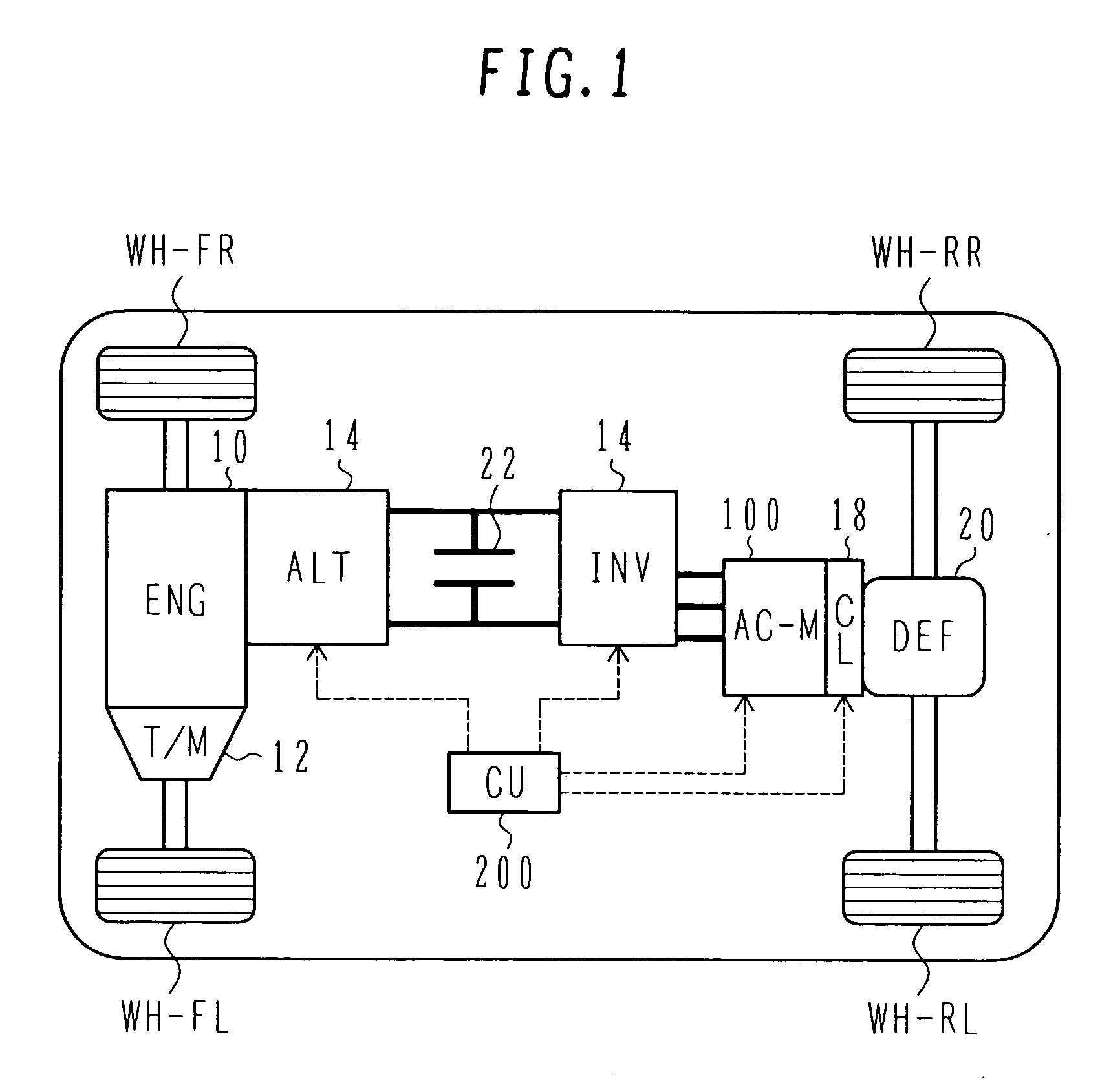
[0051]FIG. 1 is a schematic view showing the system configuration of the electric four-wheel drive vehicle according to a first embodiment of the present invention.

[0052] In the electric four-wheel drive vehicle of this embodiment, a driving force outputted from an engine (ENG) 10 is transmitted to front wheels WH-FR and WH-FL through a transmission (T / M) 12, whereby the front wheels WH-FR and WH-FL are driven. Also, the engine 10 drives a generator (ALT) 14. The generator 14 is, e.g., of the type capable of variably outputting electric power up to a voltage higher than that of a generator adapted for a 14-V power supply which is used to supply electric power to onboard auxiliaries, such as a ...

second embodiment

[0118] The construction of an electric four-wheel drive vehicle according to the present invention will be described below with reference to FIGS. 12 and 13.

[0119]FIG. 12 is a schematic view showing the system configuration of the electric four-wheel drive vehicle according to the second embodiment of the present invention. FIG. 13 is a flowchart showing control procedures for the electric four-wheel drive vehicle according to the second embodiment of the present invention. In FIG. 12, the same reference numerals as those in FIG. 1 denote the same components.

[0120] As shown FIG. 12, an engine (ENG) 10 generates motive power for driving front wheels WH-FR and WH-FL, and is connected a generator (ALT2) 40 for a 12-V battery, a compressor (COMP) 42 for an air conditioner, and a 60-V high-voltage generator 14 as a motive power source for a synchronous motor (AC-M) 100 that drives rear wheels. In addition, an electric power steering (EPS) motor 44, an electric brake (E-BR) motor 46, etc...


PUM


Abstract

A synchronous motor with low vibrations and an electric driving system using the motor. A field-coil synchronous motor comprises a stator and a rotor rotatably supported at the inner peripheral side of the stator with a gap left relative to the stator. The stator has a stator coil supplied with electric power while being controlled such that driving torque is reduced as a rotation speed of the rotor increases, and the rotor has a field coil supplied with a field current while being controlled such that the field current is reduced as the rotation speed of the rotor increases. The rotor is a tandem claw-pole rotor comprising plural pairs of N- and S-claw poles disposed side by side in an axial direction, and the plural pairs of claw poles of said tandem claw-pole rotor are relatively shifted from each other in a circumferential direction.

Description

BACKGROUND OF THE INVENTION [0001] 1. Field of the Invention [0002] The present invention relates to a synchronous motor and an electric driving system for use in an electric four-wheel drive vehicle in which front wheels are rotated by a driving force from an engine and rear wheels are rotated by a driving force from a motor. [0003] 2. Description of the Related Art [0004] Recently, vehicles running with motors used as driving sources have become increasingly popular. They are called eco-friendly cars and represented by electric vehicles and hybrid vehicles. As major features, each of those vehicles mounts a battery and has the function of utilizing electric power of the battery to generate torque from a motor for driving of the vehicle. In an electric vehicle, the battery is charged using an onboard or external charger. In a hybrid vehicle, the battery is charged by driving a generator with an engine (or causing a motor to generate electric power). [0005] Along with the eco-friend...

Claims


Application Information

Patent Timeline
Patent Type & Authority Applications(United States)
IPC IPC(8): H02K16/02H02K19/00H02P1/46B60L50/16B60L50/15H02K19/24H02P6/06H02P6/08H02P6/17H02P6/32H02P21/00H02P21/06H02P21/08H02P27/06H02P27/08
CPCB60K6/26Y02T10/725B60K6/46B60K6/52B60L11/123B60L11/14B60L11/1803B60L15/025B60L2210/20B60L2220/12B60L2220/14B60L2260/28H02K3/28H02K16/00H02K19/16H02P2207/05Y02T10/6217Y02T10/623Y02T10/6265Y02T10/641Y02T10/643Y02T10/7005Y02T10/7077B60K6/44B60L50/61B60L50/16B60L50/51Y02T10/62Y02T10/64Y02T10/72Y02T10/70Y02T10/7072
Inventor UMESAKI, YOSUKEKOBAYASHI, TAKASHIYOSHIDA, KENICHINISHIDATE, KEISUKETAHARA, KAZUO
Owner HITACHI LTD
Why Eureka
Try Eureka