Control circuit and control method of current mode control type DC-DC converter

a control circuit and converter technology, applied in dc-dc conversion, power conversion systems, climate sustainability, etc., can solve problems such as unstable operation and over-duty, and achieve the effects of preventing subharmonic oscillation of coil current, and preventing output current drop

Active Publication Date: 2006-09-14
CYPRESS SEMICON CORP
View PDF14 Cites 25 Cited by
  • Summary
  • Abstract
  • Description
  • Claims
  • Application Information

AI Technical Summary

Benefits of technology

[0014] Hence, the DC-DC converter control circuit and DC-DC converter control method of the invention are intended to control the coil current IL directly so that the lower limit of the coil current may become the lower limit determined by the second setting unit. As a result, the lower limit of the coil current can be set uniformly at a constant value. Hence, in the current mode control type DC-DC converter for turning off and controlling the main transistor by detecting the current flowing in the coil, even if the on-duty exceeds 50%, subharmonic oscillation of coil current can be prevented.
[0015] Further, when detecting the coil current value in the current detector, it is not necessary to make correction such as slope compensation regardless of the detected coil current value. Hence, in a region of on-duty exceeding 50%, the amount of current of the coil current actually flowing in the coil can be detected correctly. Therefore, subharmonic oscillation of coil current is prevented, and drop of output current can be prevented at the same time.

Problems solved by technology

However, problems occur when the on-duty exceeds 50%.
As a result, the operation becomes unstable.

Method used


Image

  • Control circuit and control method of current mode control type DC-DC converter
  • Control circuit and control method of current mode control type DC-DC converter
  • Control circuit and control method of current mode control type DC-DC converter

Examples


Embodiment Construction

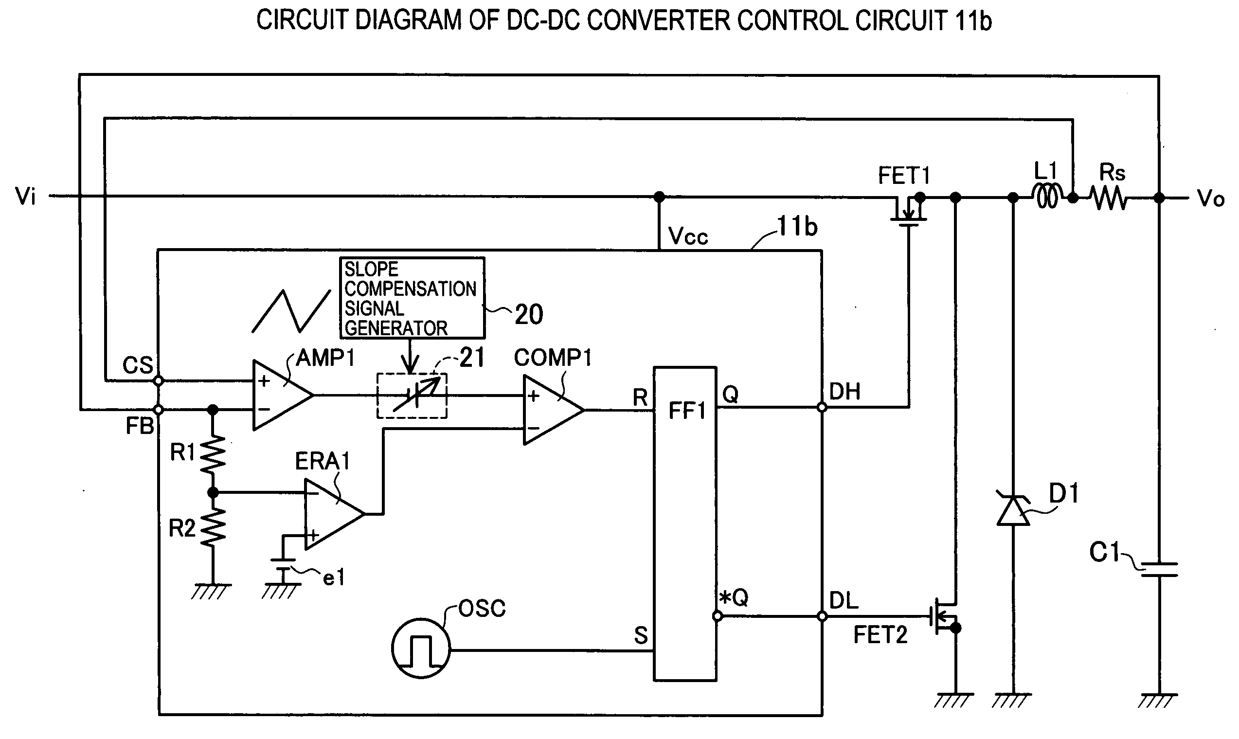
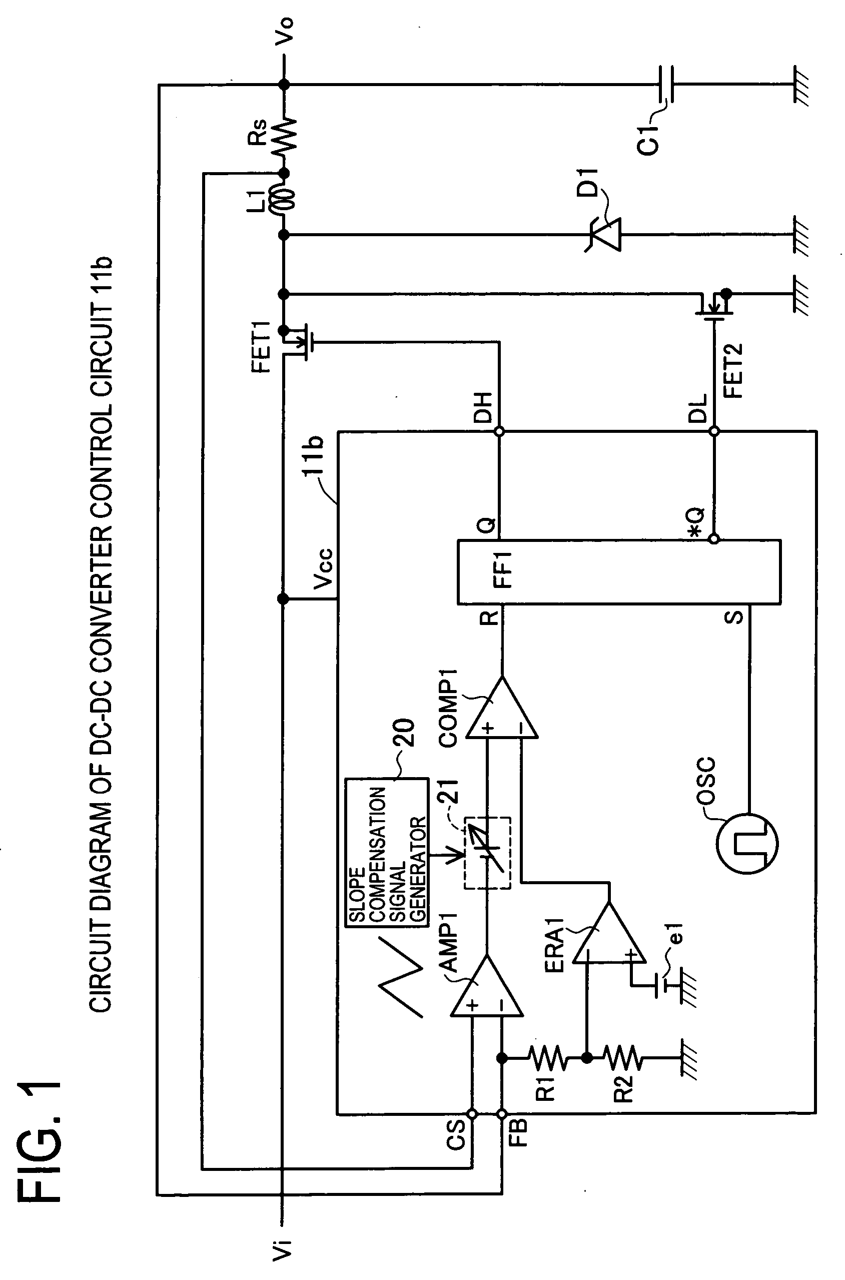
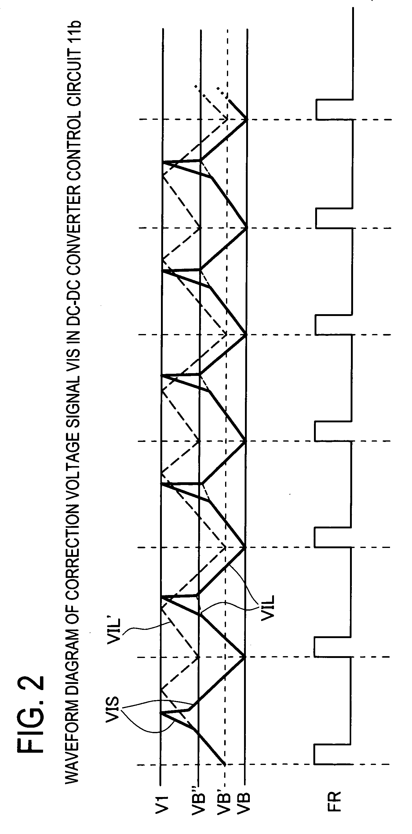
[0029] First and second preferred embodiments of the invention are described by referring to FIG. 1 to FIG. 9. The first preferred embodiment is explained in FIG. 1 to FIG. 4. First, in the case of the on-duty of main transistor exceeding 50%, a conventional method (slope compensation control) for canceling effects of subharmonic oscillation is explained by referring to FIG. 1 and FIG. 2. When the on-duty is 50% or more, as shown in FIG. 12, coil current IL may induce subharmonic oscillation. To avoid such problem, so-called slope compensation control is attempted. FIG. 1 is a circuit diagram of DC-DC converter control circuit 11b for slope compensation control. The DC-DC converter control circuit 11b comprises, in addition to a conventional DC-DC converter control circuit 101, a slope compensation signal generator 20, and a signal synthesis unit 21. Other structure is same as in the DC-DC converter 100 in FIG. 11, and the explanation is omitted.

[0030]FIG. 2 shows a waveform of out...


PUM


Abstract

The invention presents a control circuit and a control method of DC-DC converter capable of suppressing subharmonic oscillation of coil current even if the on-duty is over 50%. An error amplified signal V1 is an output voltage of an error amplifier ERA1. An offset voltage unit Ve2 outputs a lower limit set voltage V2 obtained by subtracting offset voltage e2 from error amplified signal V1. A voltage comparator COMP2 compares lower limit set voltage V2 output from offset voltage Ve2, and output voltage signal VIL. When the voltage value of output voltage signal VIL is decreased to lower limit set voltage V2 (region E2), the output of voltage comparator COMP2 changes from low level to high level. As a result, main transistor FET1 is set in conductive state. On the other hand, when the voltage value of output voltage signal VIL reaches an error amplified signal V1 (region E1), main transistor FET1 is set in non-conductive state.

Description

CROSS-REFERENCE TO RELATED APPLICATIONS [0001] This application is based upon and claims the benefit of priority from each of the prior Japanese Patent Application No. 2005-067355 filed on Mar. 10, 2005, the entire contents of which are incorporated herein by reference. BACKGROUND OF THE INVENTION [0002] 1. Field of the Invention [0003] The present invention relates to a control circuit and a control method of current mode control type DC-DC converter, and more particularly to prevention of subharmonic oscillation in the event of on-duty exceeding 50%. [0004] 2. Description of the Related Art [0005] A current mode control type DC-DC converter for duty control by detecting the current flowing in a choke coil and turning off and controlling the main switching transistor is likely to induce subharmonic oscillation when the on-duty exceeds 50%. FIG. 11 is a diagram of a conventional current mode control type DC-DC converter 100. FIG. 11 is a circuit diagram of a general step-down DC-DC ...

Claims


Application Information

Patent Timeline
Patent Type & Authority Applications(United States)
IPC IPC(8): G05F1/00
CPCH02M1/44H02M3/157H02M3/1588Y02B70/1466Y02B70/10
Inventor NISHIMORI, EIJI
Owner CYPRESS SEMICON CORP
Why Eureka
Try Eureka