Picture element using microelectromechanical switch

a micro-electromechanical switch and picture element technology, applied in the field of switches, can solve the problems of difficult to achieve in emerging applications requiring flexible displays, difficult to manufacture pixel mechanisms, and increase the stress on display components, so as to improve off-axis contrast and on-axis contrast, and reduce the effect of bending

Inactive Publication Date: 2006-09-14
SEERTECH CORP
View PDF5 Cites 90 Cited by
  • Summary
  • Abstract
  • Description
  • Claims
  • Application Information

AI Technical Summary

Benefits of technology

[0024] A fourteenth embodiment represents a steering mechanism that includes an electrostatic switch and an occultating disk array, wherein the occultating disk array is independently translatable in a plurality of directions, and wherein the steering mechanism is configured to steer an image from a display without

Problems solved by technology

Design and manufacture of pixel mechanisms can be particularly important yet difficult to achieve in emerging applications requiring flexible displays.
In such applications, bending may place additional

Method used


Image

  • Picture element using microelectromechanical switch
  • Picture element using microelectromechanical switch
  • Picture element using microelectromechanical switch

Examples


first embodiment

[0011] Additional embodiments of the present invention include a first embodiment corresponding to a display system. The display system includes a micro electromechanical system (MEMS) switch; an electrophoretic display material coupled to the switch; and an array decoder coupled to the switch and the electrophoretic display material, the array decoder being configured to detect a touched pixel location.

second embodiment

[0012] A second embodiment represents a sign display system that includes a flat panel display (FPD) and a secure memory component, wherein the secure memory component is configured to store information for controlling display contents on the FPD.

third embodiment

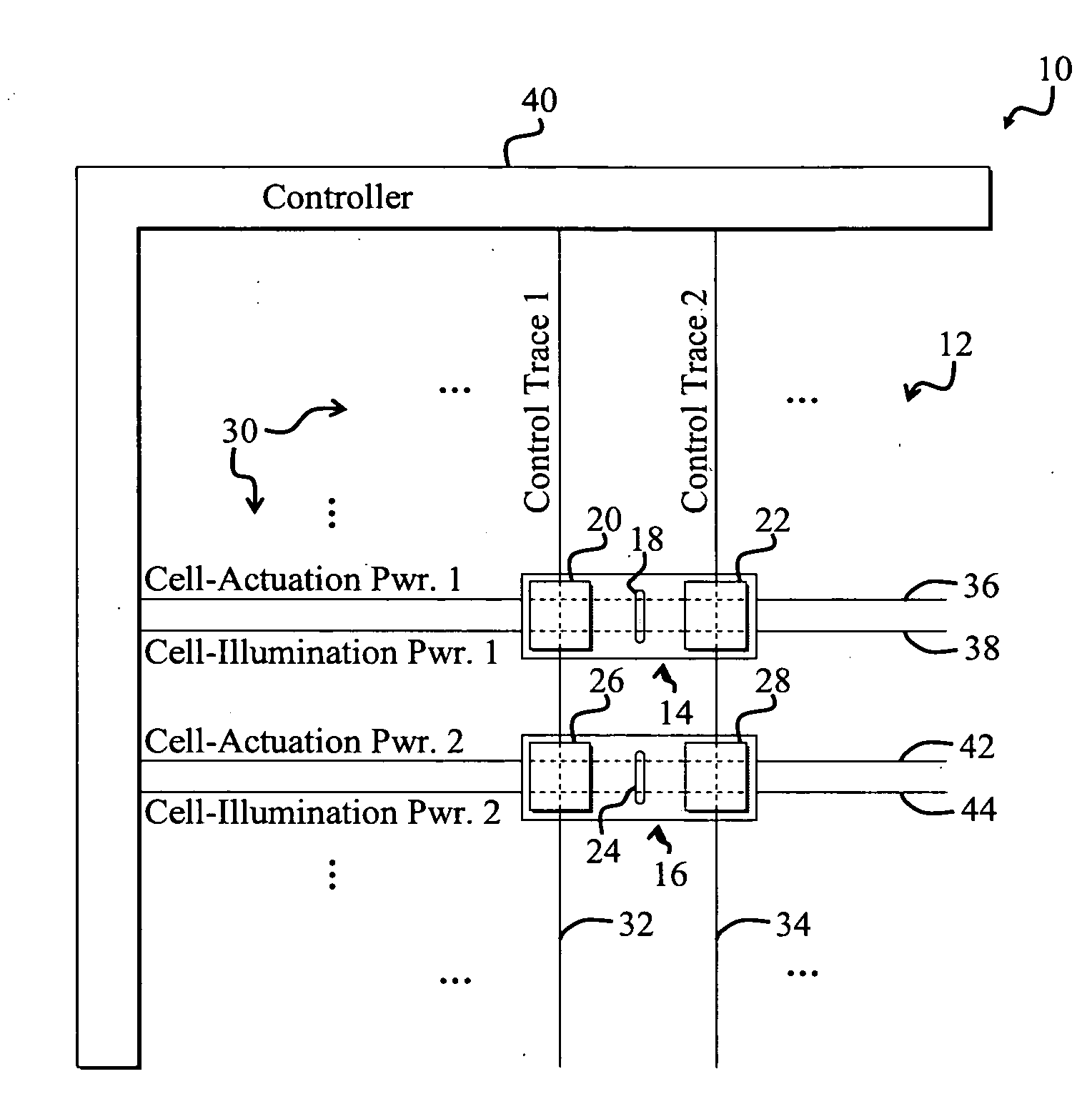
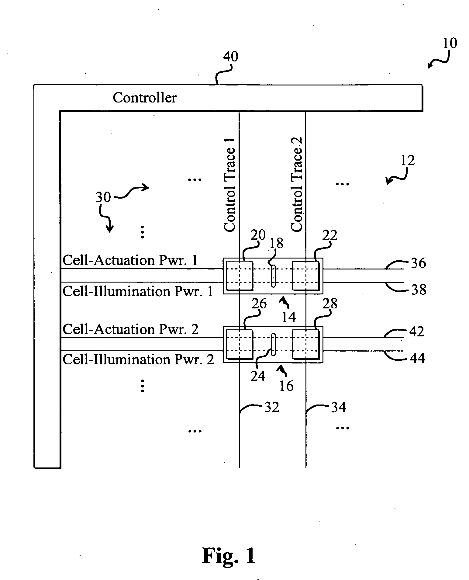
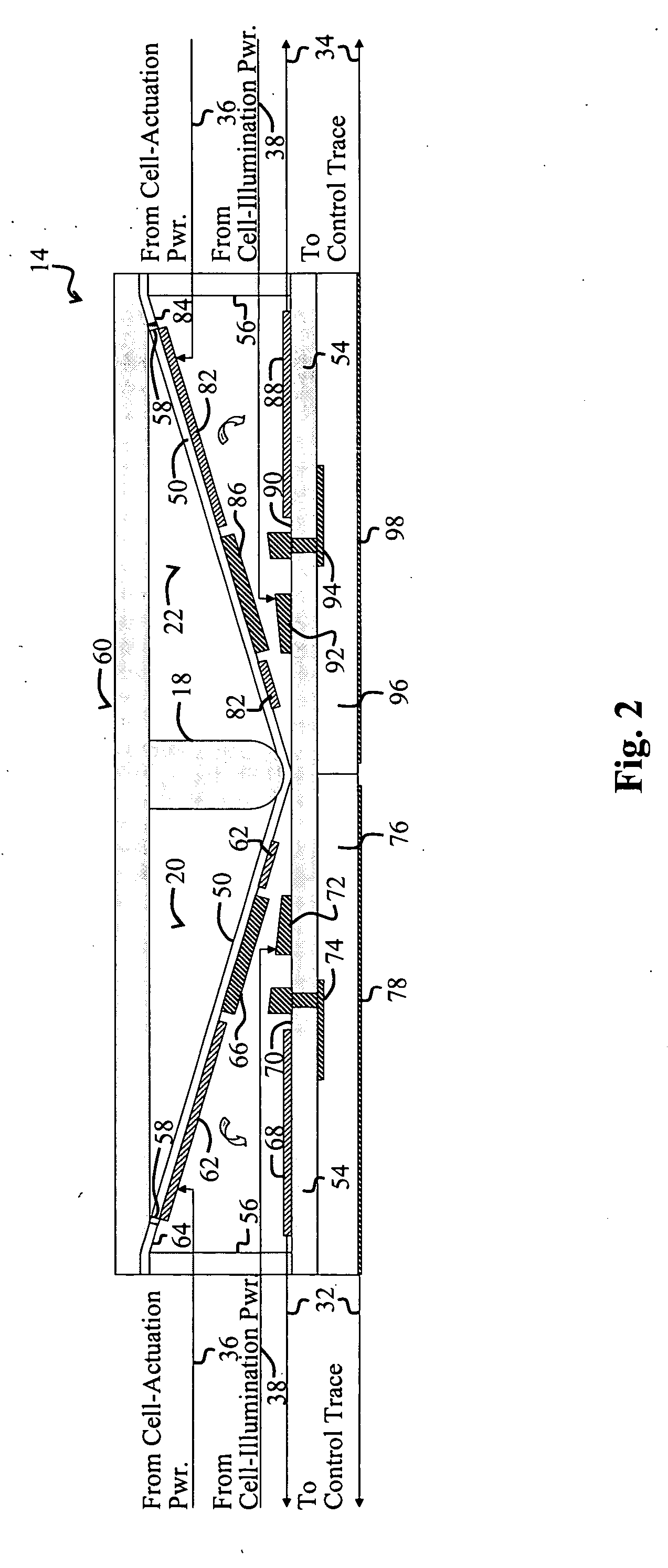
[0013] A third embodiment represents a switch arrangement that includes a substantially parallel arrangement of a first power, ground, and a second power, wherein the first and second powers each include a plurality of via structures and a light emitting diode (LED) device is substantially aligned with the ground and the first power.


PUM


Abstract

A robust microelectromechanical switch. In an illustrative embodiment, the switch is adapted for use in a display and includes a first flexible surface and a second surface. The second surface is angled relative to the first surface, forming a wedge the first surface and the second surface. A first terminal and a second terminal are positioned relative to the first flexible surface and the second surface so that selective flexing of the flexible surface electrically couples or uncouples the first terminal to the second terminal. In a more specific embodiment, the switch further includes a first mechanism for selectively applying an electrostatic force between the first flexible surface and the second surface. The first surface is positioned on a first elastic flexible layer, and the second surface is positioned on a second layer. The first mechanism includes a first actuator electrode that is coupled to the first surface, and a second actuator electrode that is coupled to the second surface. A sufficient charge differential applied between the first actuator electrode and the second actuator electrode will attract the first electrode to the second electrode, thereby flexing the flexible layer toward the second layer. The sidewalls define a perimeter of a cell that houses the switch. A protrusion extends from a third layer between the sidewalls, thereby indenting the first layer, and thereby forming the wedge.

Description

CLAIM OF PRIORITY [0001] This invention claims priority from commonly assigned U.S. Provisional Patent Application Ser. No. 60 / 656,855, entitled MICRO-ELECTROMECHANICAL SWITCH, filed on Feb. 25, 2005, which is hereby incorporated by reference as if set forth in full in this application for all purposes.BACKGROUND OF THE INVENTION [0002] This invention is related in general to switches and more specifically to electrically controllable switches suitable for controlling optical devices, such as pixels of a display. [0003] Displays, including passive and active matrix Liquid Crystal Displays (LCDs) and plasma displays, are employed in various demanding applications, including cell phone screens, electric billboards, televisions, calculator screens, wristwatch screens, and electronic paper. Such applications often demand robust cost-effective display cells, often called picture elements, or “pixels,” that can be employed to reliably produce images when combined in a display. [0004] Desi...

Claims


Application Information

Patent Timeline
IPC IPC(8): G09G3/36
CPCH01H1/645H01H59/0009
Inventor PASCH, NICHOLAS F.SAUVANTE, MICHAEL D.SANDERS, GLENN C.SENDA, KAZUOSEKI, HAJIME
Owner SEERTECH CORP
Why Eureka
Try Eureka