Zoom optical system

a technology of optical system and zoom, applied in the field of zoom optical system, can solve the problems of maintaining good optical performance over the entire zoom range, and achieve the effects of compactness, optical performance, and compactness

Active Publication Date: 2006-09-14
FUJI PHOTO OPTICAL CO LTD
View PDF12 Cites 9 Cited by
  • Summary
  • Abstract
  • Description
  • Claims
  • Application Information

AI Technical Summary

Benefits of technology

[0008] The present invention relates to an inexpensive zoom optical system with a simpler construction than previous zoom optical systems, but that has a compactness, zoom ratio, and optical performance that are at least equal to that of previous zoom optical systems.

Problems solved by technology

However, with this two-group construction of lens groups having negative and positive refractive power arranged in order from the object side, because the entire lens system becomes asymmetric and fluctuations in aberrations during zooming increase, if the lens system is to provide a bright image, maintaining good optical performance over the entire zoom range is a problem.

Method used


Image

  • Zoom optical system
  • Zoom optical system
  • Zoom optical system

Examples


embodiment 1

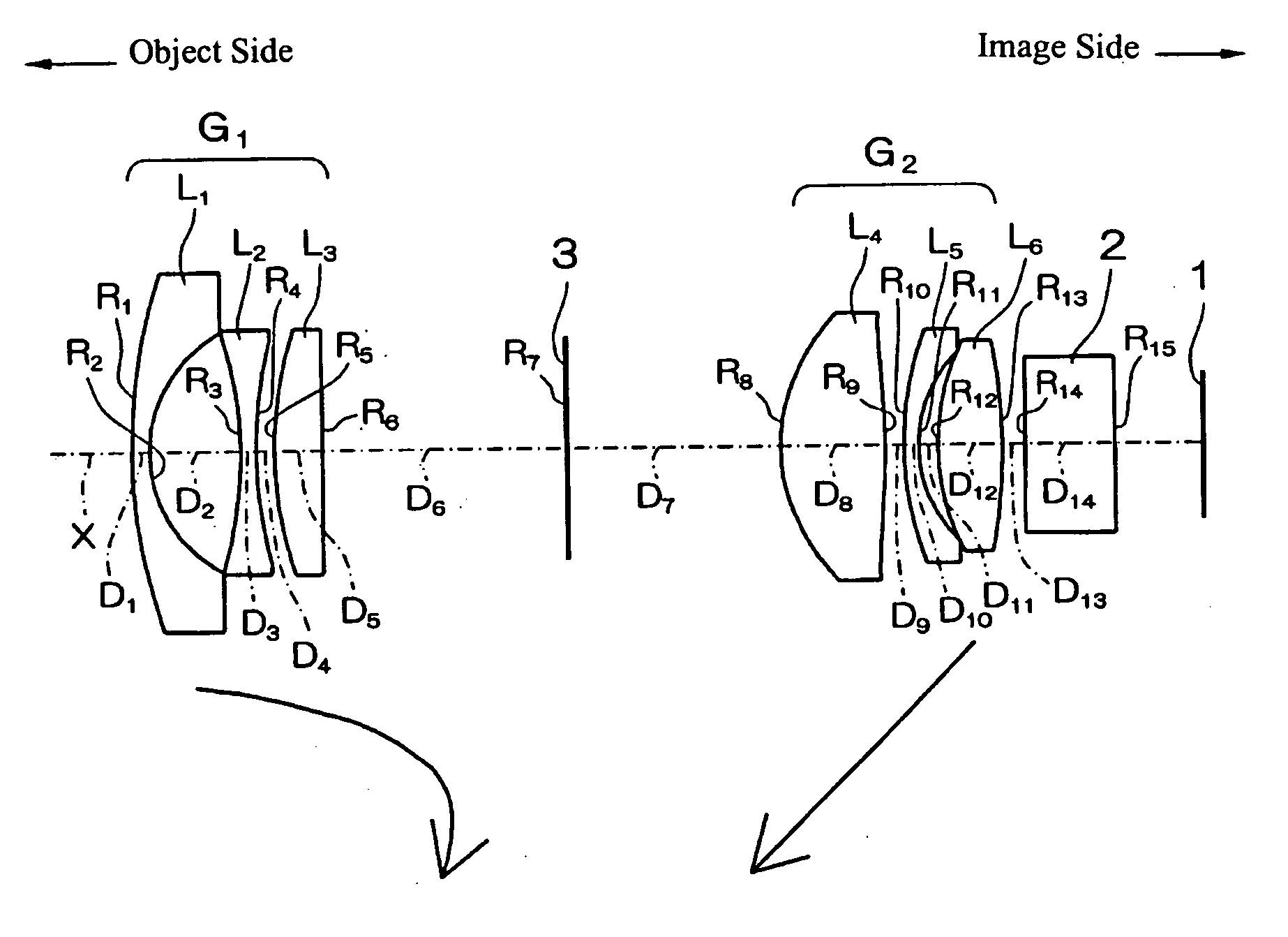
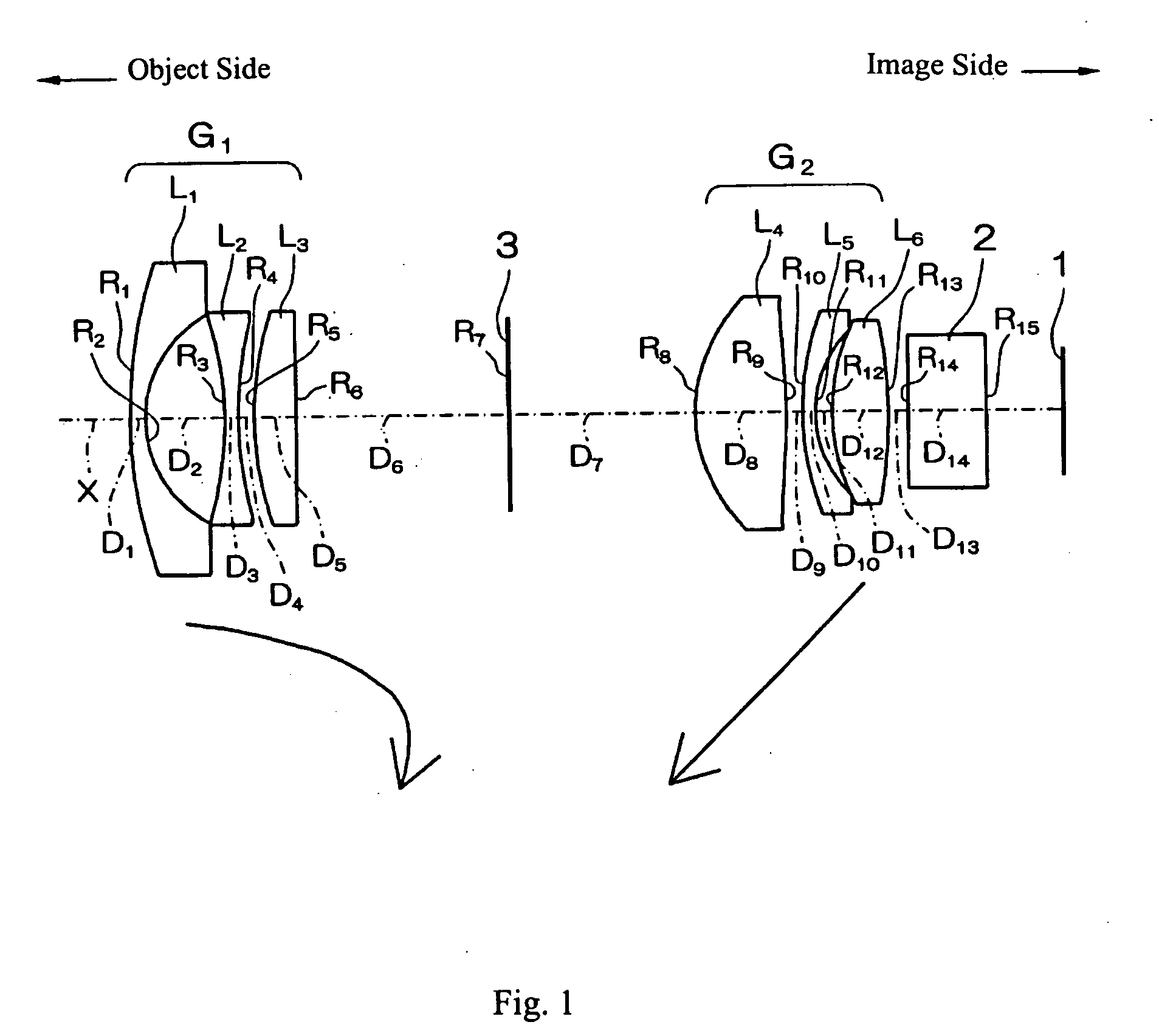
[0049]FIG. 1 shows a cross-sectional view of Embodiment 1 of the zoom optical system of the present invention at the wide-angle end.

[0050] Table 1 below lists the surface number #, in order from the object side, the radius of curvature R (in mm) of each surface on the optical axis, the on-axis surface spacing D (in mm), except that the on-axis surface spacings that vary with zooming are listed in Table 3 below, as well as the refractive index Nd and the Abbe number νd at the d-line (587.6 nm) of each optical element for Embodiment 1. Note that although R is the on-axis radius of curvature, for convenience of illustration, in FIG. 1 the lead lines from the R reference symbols extend to the surfaces being referenced but do not extend to the on-axis positions.

TABLE 1#RDNdνd124.34510.801.8040046.626.06684.123−17.42770.701.7725049.6419.54610.80516.76532.201.8466623.86−584.5234D6 (variable)7∞ (stop)D7 (variable) 8*7.46274.681.6935053.2 9*−31.73720.8610 14.13130.651.9228618.911 5.98270....

embodiment 2

[0057]FIG. 3 shows a cross-sectional view of Embodiment 2 of the zoom optical system of the present invention at the wide-angle end.

[0058] Table 5 below lists the surface number #, in order from the object side, the radius of curvature R (in mm) of each surface on the optical axis, the on-axis surface spacing D (in mm), except that the on-axis surface spacings that vary with zooming are listed in Table 7 below, as well as the refractive index Nd and the Abbe number νd at the d-line (587.6 nm) of each optical element for Embodiment 2. Note that although R is the on-axis radius of curvature, for convenience of illustration, in FIG. 3 the lead lines from the R reference symbols extend to the surfaces being referenced but do not extend to the on-axis positions.

TABLE 5#RDNdνd121.64930.801.8348142.726.24234.693−16.38961.191.8348142.7425.16010.88521.49842.261.9228618.96−247.8664D6 (variable)7∞ (stop)D7 (variable) 8*7.79184.531.6935053.2 9*−31.25870.9410 12.82780.651.9228618.911 6.04201....

embodiment 3

[0064]FIG. 5 shows a cross-sectional view of Embodiment 3 of the zoom optical system of the present invention at the wide-angle end.

[0065] Table 9 below lists the surface number #, in order from the object side, the radius of curvature R (in mm) of each surface on the optical axis, the on-axis surface spacing D (in mm), except that the on-axis surface spacings that vary with zooming are listed in Table 11 below, as well as the refractive index Nd and the Abbe number νd at the d-line (587.6 nm) of each optical element for Embodiment 3. Note that although R is the on-axis radius of curvature, for convenience of illustration, in FIG. 5 the lead lines from the R reference symbols extend to the surfaces being referenced but do not extend to the on-axis positions.

TABLE 9#RDNdνd119.19390.941.8040046.626.32253.973−31.59651.201.8040046.6411.87482.18515.54811.831.9228618.9639.0734D6 (variable)7∞ (stop)D7 (variable) 8*7.47394.671.6935053.2 9*−38.67791.0210 13.46760.651.9228618.911 5.65710.8...


PUM


Abstract

A simple two-group zoom optical system that favorably corrects aberrations includes, in order from the object side, a first lens group of negative refractive power, a stop, and a second lens group of positive refractive power. The first lens group includes, in order from the object side, a lens element having negative refractive power and a meniscus shape with its concave surface on the image side, a biconcave lens element, and a lens element having positive refractive power. The second lens group includes, in order from the object side, a lens element having positive refractive power and at least one aspheric surface, a lens element having negative refractive power, and a biconvex lens element. Certain conditions are satisfied that relate to the focal lengths of the zoom optical system, the focal lengths of the two lens groups, and to the Abbe numbers of lens elements.

Description

TECHNICAL FIELD OF THE INVENTION [0001] The present invention relates to a zoom optical system with a field angle of about one hundred thirty degrees that can be used in various kinds of video cameras and electronic still cameras that include CCDs (Charge Coupled Devices) as image detectors, and relates particularly to a small, wide-angle zoom optical system with a high variable power. BACKGROUND OF THE INVENTION [0002] There is an increased demand for monitoring cameras to operate in unmanned installations at night, and such cameras with zooming capabilities have recently been sought. Such a zoom optical system for a monitoring camera requires the ability to identify an object even in an environment of low illumination and that the zoom optical system is capable of providing a wide field angle (i.e., a wide-angle of view). However, it has also been increasingly desired that the zoom optical system be compact, have a high zoom ratio, and provide good optical performance throughout t...

Claims


Application Information

Patent Timeline
Patent Type & Authority Applications(United States)
IPC IPC(8): G02B15/14
CPCG02B15/177
Inventor TOMIOKA, UKYO
Owner FUJI PHOTO OPTICAL CO LTD
Why Eureka
Try Eureka