Optical regenerative amplifier for binary phase shift-keying signals

a phase shift-keying signal and optical regenerative amplifier technology, applied in the direction of electromagnetic transmission, electrical equipment, transmission, etc., can solve the problems of inventions that cannot be used for regeneration of phase shift-keying optical signals, inventions that cannot be used for regenerating relative optical phases of transmitted signals, etc., to achieve the effect of improving signal-to-noise ratio and reducing phase and amplitude nois

Inactive Publication Date: 2006-09-14
GRIGORYAN VLADIMIR
View PDF34 Cites 12 Cited by
  • Summary
  • Abstract
  • Description
  • Claims
  • Application Information

AI Technical Summary

Benefits of technology

[0008] According to the first aspect of the invention, there is provided an optical regenerative amplifier device for performing all-optical regeneration of optical BPSK sequence of signals (pulses). The BPSK signals may be parts of the QPSK signals (pulses) with at least two signals (pulses), wherein the relative phase between the adjacent pulses is either 0 or π radian. In particular though not exclusively, the BPSK sequence of pulses represents a sequence of pulses with the same phases and the relative optical phase of zero radians between any two pulses in the sequence. The regenerative amplifier comprises three units. The first unit is a first delay interferometer, wherein a BPSK sequence of signals is converted into two mutually anti-symmetric ASK trains of signals. An asymmetric Mach-Zehnder interferometer can be used as the firs

Problems solved by technology

However, these inventions are not able of regenerating relative optical phase of the transmitted signals.
Consequ

Method used


Image

  • Optical regenerative amplifier for binary phase shift-keying signals
  • Optical regenerative amplifier for binary phase shift-keying signals
  • Optical regenerative amplifier for binary phase shift-keying signals

Examples


Embodiment Construction

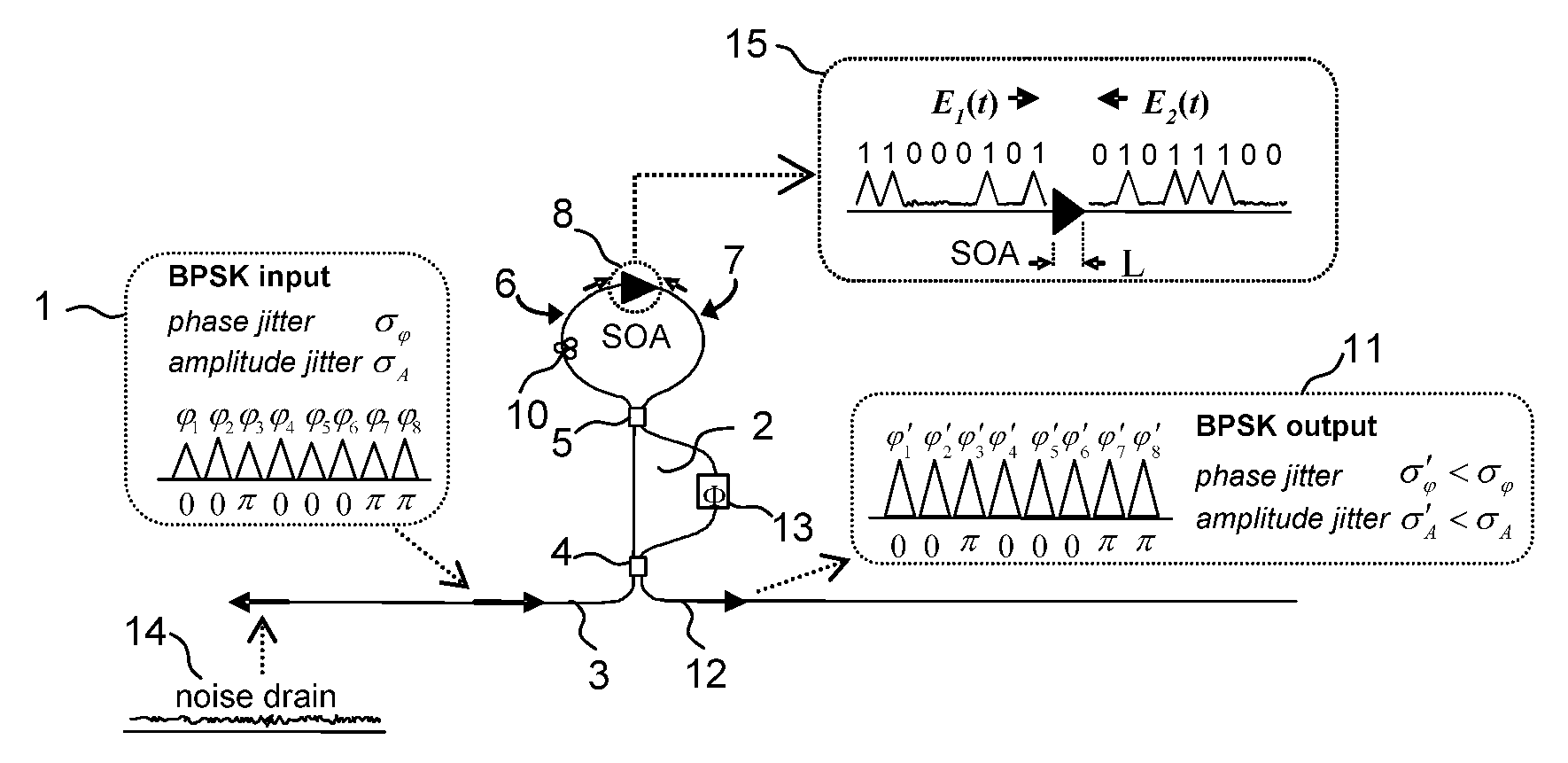
[0022] The optical regenerative amplifier claimed in this invention enables regeneration of the relative optical phase of the transmitted signals by means of interfering the adjacent optical signals in a delay interferometer, suppressing the residual destructive interference product relative to the constructive interference product, and amplifying the constructive interference product in a limiting amplifier, thereby forcing the relative optical phase in any pair of optical signals to be either 0 or π radian and equalizing the amplitudes of the optical signals. Therefore the present optical regenerative amplifier can be used for optical regeneration of the optical phase shift-keying signals.

[0023]FIG. 1 illustrates a device and method for performing all-optical regeneration of multiple signals comprising a sequence of optical BPSK signals (pulses). The BPSK signals may be parts of the QPSK signals (pulses) with at least two signals (pulses), wherein the relative phase between the a...


PUM


Abstract

There is provided an optical regenerative amplifier for regenerative amplification of a binary phase shift-keying (BPSK) sequence of optical signals having a predetermined time slot between any adjacent signals. The optical regenerative amplifier comprises a first delay interferometer, wherein an input sequence of BPSK signals is split between two arms of an interferometer, a relative delay by the time slot between the adjacent signals is introduced in one of the arms of the interferometer to produce two mutually anti-symmetric trains of amplitude shift-keying (ASK) signals; a discriminative limiting amplifier to amplify the said two trains of anti-symmetric ASK signals, wherein the amplification for the spaces is smaller compared to the amplification for the marks and the amplification for the marks is limiting; and a second delay interferometer, wherein the said two trains of anti-symmetric ASK signals are recombined, delayed, and interfered to reproduce a regeneratively amplified BPSK sequence of signals and to separate noise from the signals.

Description

RELATED APPLICATIONS [0001] This application claims the benefit of provisional application Ser. No. 60 / 656,987 filed Feb. 28, 2005.[0002] This invention was made at Northwestern University, Evanston, Ill. 60208, with government support under the following grant: DARPA-AFRL No. F 30602-01-2-0528 / P00007. Both the Northwestern University and the government released their rights in this invention to the inventors.BACKGROUND OF THE INVENTION [0003] 1. Field of the Invention [0004] This invention is directed to regeneration of both amplitude and phase of optical binary phase shift-keying (BPSK) signals used in three areas: first, data communication by means of optical BPSK modulation format, second, data communication by means of optical quadrature phase shift-keying (QPSK) modulation format, wherein the BPSK signals constitute parts of the QPSK signals, and third, harmonically mode-locked lasers. In the BPSK signals the relative optical phase between the signals in adjacent time slots is...

Claims


Application Information

Patent Timeline
IPC IPC(8): H04B10/00
CPCH04B10/299
Inventor GRIGORYAN, VLADIMIRKUMAR, PREM
Owner GRIGORYAN VLADIMIR
Why Eureka
Try Eureka