Annular safety and flow control system for underground gas storage

a flow control system and flow control technology, applied in the direction of loading/unloading, well/borehole valve arrangement, borehole/well accessories, etc., can solve the problems of inconvenient operation, inability to safely shut off the well, and inability to provide the high flow rate that is necessary. , to achieve the effect of safety and flow control, quick shutting off flow, and convenient construction

Active Publication Date: 2006-09-14
BAKER HUGHES INC
View PDF21 Cites 7 Cited by
  • Summary
  • Abstract
  • Description
  • Claims
  • Application Information

AI Technical Summary

Benefits of technology

[0009] The invention provides a control system for a gas storage well that affords total annular control of flow into and out of the storage well. In addition, the control system is inexpensive and readily constructed from standard, off-the-shelf components and without the need for expensive specialized tools. In a preferred embodiment described herein, a gas storage well is provided with a tubing string that is disposed within a wellbore communicating an underground storage cavern with the surface. Suitable piping and valves are provided at the wellhead to provide gas flow into the cavern via the annulus surrounding the tubing string and simultaneous water flow out of the cavern via the flowbore of the tubing string. In addition, gas can be flowed out of the cavern through both the annulus and the flowbore.
[0010] A surface controlled subsurface safety and flow control system is provided within the wellbore so that all flow into or out of the well can be shut down rapidly in the event of an emergency. In a preferred embodiment, the safety and flow control system is provided by a dual opening-style packer element that provides an annulus seal between the surrounding casing and the tubing string and between the casing and a pup joint that is located within the annulus. Both the tubing string and the pup joint contain surface controlled subsurface safety valves that are capable of quickly shutting off flow through both the flowbore and the annulus. Each valve can be opened or closed independently of the other. The safety and flow control system allows use of essentially the entire annulus as well as the flowbore of the tubing string for production of gas from the well. This type of system allows significantly higher rates of production than with prior systems.

Problems solved by technology

Conventional flow control systems are generally unable to provide the high flow rates that are necessary.
Wellhead tree valves are not useful in the event of an emergency requiring that gas flow be shut off at a point well below the surface of the well.
If there is no subsurface safety valve present, the well cannot be safely shut off in the event of an emergency.
However, even these are not useful in an emergency where rapid shut down is required.
In general, however, these are complex tools of highly specialized construction and, as a result, quite costly.
Additionally, these arrangements are generally unable to perform simultaneous injection of gas and leaching of water.
This is undesirable.

Method used


Image

  • Annular safety and flow control system for underground gas storage
  • Annular safety and flow control system for underground gas storage
  • Annular safety and flow control system for underground gas storage

Examples


Embodiment Construction

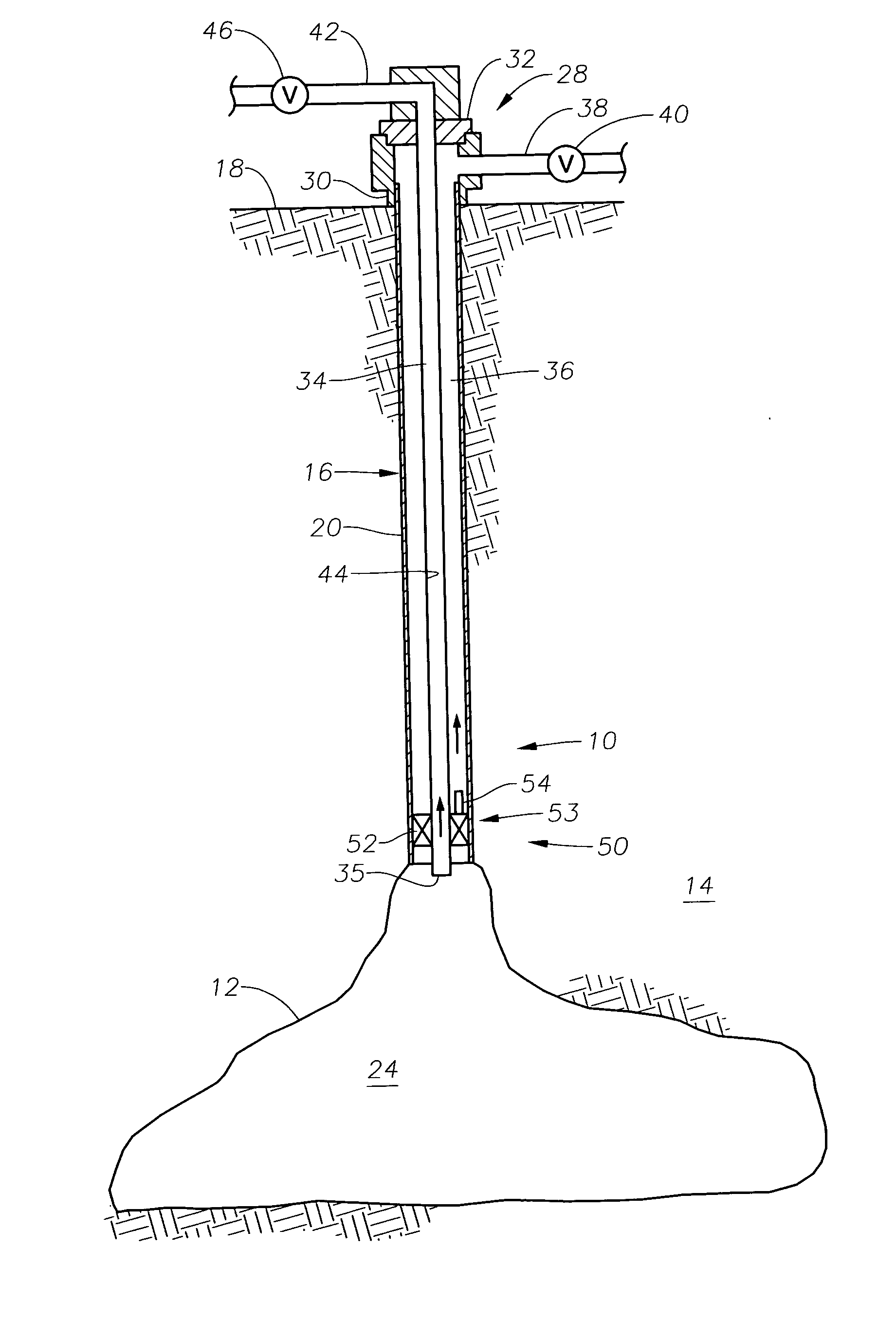
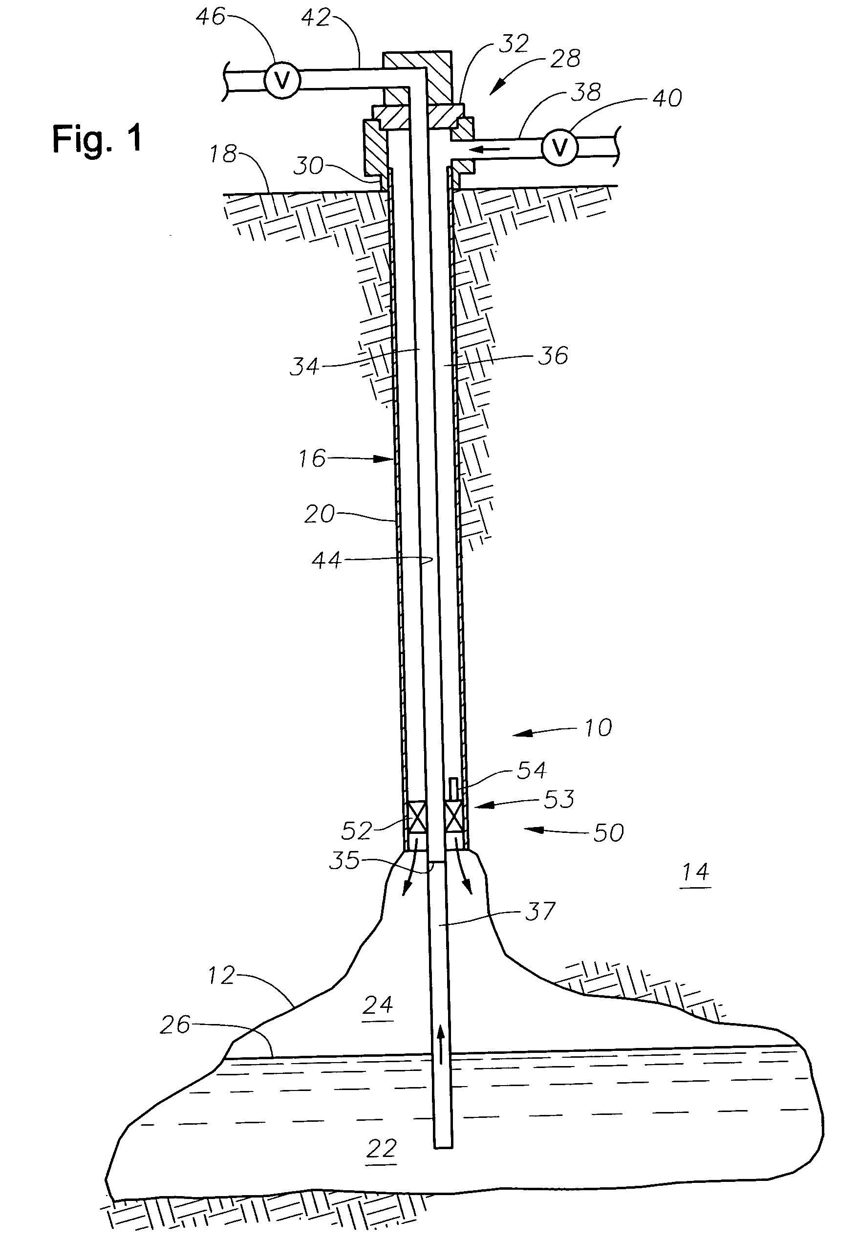
[0015]FIG. 1 illustrates an exemplary underground hydrocarbon gas storage well 10 that includes an underground cavern 12 that is typically a salt dome within the earth 14. Those of skill in the art will understand that the cavern 12 may also be provided by a depleted hydrocarbon reservoir. A wellbore 16 has been drilled through the earth 14 from the surface 18 down to the cavern 12. At least a portion of the wellbore 16 is typically lined with steel casing 20, in a manner known in the art. FIG. 1 depicts the well 10 at the outset of a gas storage operation, and therefore, the cavern 12 includes a volume of water 22 and a volume of gas 24 just above, the two being delineated by a gas / water interface 26.

[0016] A wellhead tree, generally indicated at 28, is located at the surface 18. Because the structure and operation of wellhead trees is well understood by those of skill in the art, the details of the tree 28 will only be described briefly herein. The wellhead tree 28 includes a cas...


PUM


Abstract

A gas storage well is provided with a tubing string that is disposed within a wellbore communicating an underground storage cavern with the surface. A surface controlled subsurface safety and flow control system is provided within the wellbore so that all flow into or out of the well can be shut down rapidly in the event of an emergency. The safety and flow control system features a dual opening-style packer element that provides an annulus seal between the surrounding casing and the tubing string and between the casing and a pup joint that is located within the annulus. Both the tubing string and the pup joint contain surface controlled subsurface safety valves that are capable of quickly shutting off flow through both the flowbore and the annulus. Each valve can be opened or closed independently of the other.

Description

BACKGROUND OF THE INVENTION [0001] 1. Field of the Invention [0002] The invention relates generally to well safety systems and flow control systems for underground gas storage wells and reservoirs and the like. In particular aspects, the invention relates to well safety systems having a plurality of surface controlled subsurface safety valves. [0003] 2. Description of the Related Art [0004] Storage wells are used to provide temporary underground storage for excess natural gas that has been produced. Storage wells are often located in underground salt domes, thereby providing a large underground storage cavern. In this instance, it is necessary to drill a wellbore that communicates with the surface. Gas is injected into the storage well and then removed at a later time when needed. To accomplish the injection of gas, a tubing string is typically disposed into the wellbore, suspended from a wellhead. Gas is injected down the annulus between the tubing string and the wellbore wall. Bec...

Claims


Application Information

Patent Timeline
Patent Type & Authority Applications(United States)
IPC IPC(8): B65G5/00
CPCB65G5/00
Inventor MCCOY, ALLAN R.MELEAR, DARRELL
Owner BAKER HUGHES INC
Why Eureka
Try Eureka