

Apparatus and method for CO2 recovery
a technology of apparatus and co2 recovery, applied in the direction of lighting and heating apparatus, machine/engine, separation process, etc., can solve the problem of prone to further increase of requirements for co2 emission limitation, and achieve the effect of further enhancing energy efficiency
- Summary
- Abstract
- Description
- Claims
- Application Information
AI Technical Summary
Benefits of technology
Problems solved by technology
Method used
Image

Examples
example 1
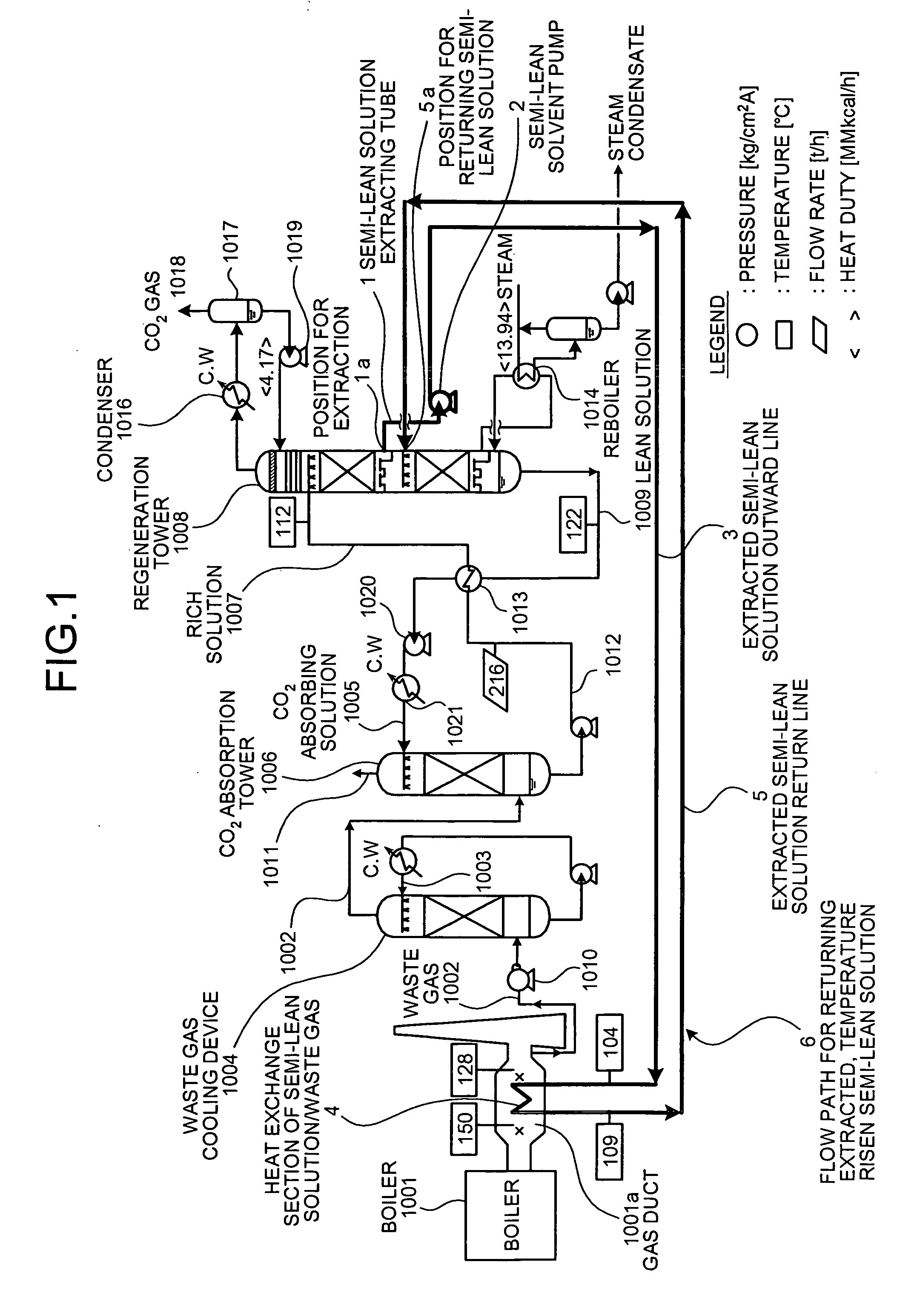
[0032]FIG. 1 is a schematic view of a CO2 recovery apparatus in Example 1 according to the present invention. In the figure, the illustration is simplified by giving the same letter and numeral to the same configuration as in the above FIG. 7.
[0033] As described above, the present invention is characterized in that the temperature profile in the regeneration tower is boosted by extracting at least a part of the semi-lean solution obtained by releasing a part or majority of CO2 from the rich solution 1007 infused into the regeneration tower 1008 at the upper part of the regeneration tower 1008, raising the temperature of the extracted semi-lean solution by performing the heat exchange with high temperature waste gas in the gas duct 1001a of the industrial facility 1001 such as boilers and gas turbines, and subsequently returning the semi-lean solution into the regeneration tower 1008 at the position below the position for extracting the semi-lean solution in the regeneration tower 1...
example 2
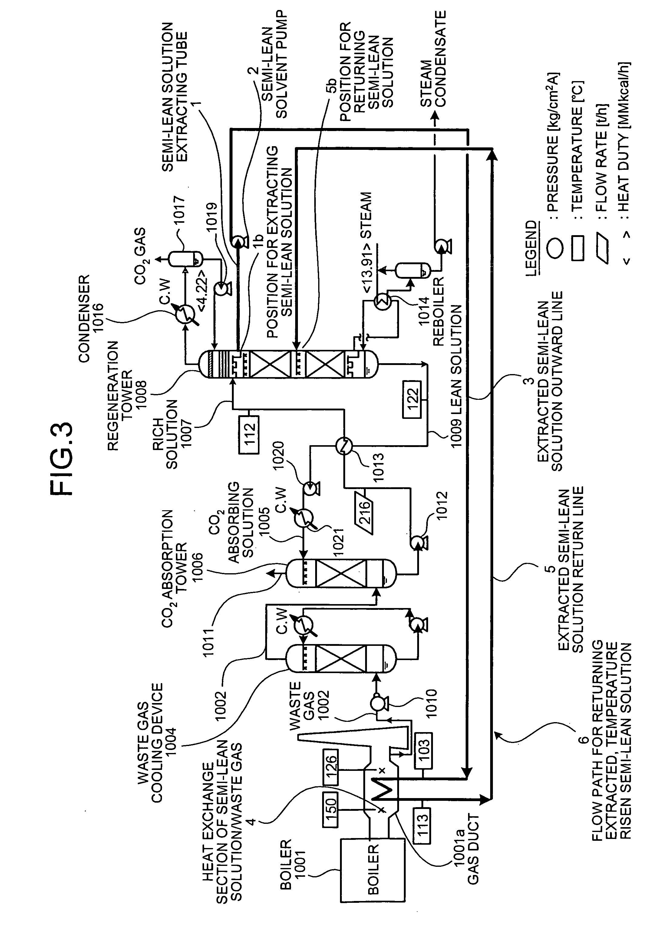
[0041]FIG. 3 is a schematic view of a CO2 recovery apparatus in Example 2 according to the present invention. In the figure, the illustration is simplified by giving the same letter and numeral to the same configuration as in the above FIG. 1. This Example 2 is different from Example 1 in that the position 1b for extracting the semi-lean solution in the regeneration tower 1008 was set in the position (4th stage) for infusing the rich solution 1007 into the regeneration tower 1008, the return position 5b of the return line 5 to the regeneration tower 1008 was set in the 6th stage and an amount of the semi-lean solution to be extracted was set as 50%.
[0042] In the present Example 2, 50% of the semi-lean solution present in the 4th stage in the regeneration tower 1008 is extracted at the position 1b for extracting the semi-lean solution provided in the 4th stage, which is the position for infusing the rich solution 1007 as described above. The temperature of this extracted semi-lean s...
example 3
[0046]FIG. 5 is a schematic view of a CO2 recovery apparatus in Example 3 according to the present invention. In the figure, the illustration is simplified by giving the same letter and numeral to the same configuration as in the above FIGS. 1 and 3. This Example 3 is different from Example 1 in that the positions for extracting the semi-lean solution in the regeneration tower 1008 are set in two positions (positions 11a and 21a ) and the semi-lean solution is returned at one return position 35b in the regeneration tower 1008 by running the return lines 15 and 25 of the flow paths 16 and 26 for returning extracted, temperature risen semi-lean solution together into one return line 35 in a last half.
[0047] The position 11a for extracting is located in the 4th stage same as in Example 2, and the position 21a for extracting is located in the 6th stage same as in Example 1. The outward lines 11 and 21 are formed into helical shapes to configure the heat exchange sections 14 and 24 of s...
PUM
| Property | Measurement | Unit |
|---|---|---|
| Temperature | aaaaa | aaaaa |
| Temperature | aaaaa | aaaaa |
| Temperature | aaaaa | aaaaa |
Abstract
Description
Claims
Application Information