
MEMS flow module with piston-type pressure regulating structure

a technology of flow module and piston, which is applied in the field of microfabricated devices, can solve problems such as damage to optic nerves, and achieve the effects of reducing fluid potential, increasing rigidity of mems flow module, and increasing flow through the mems flow modul

Inactive Publication Date: 2006-09-14
BECTON DICKINSON & CO
View PDF99 Cites 11 Cited by
  • Summary
  • Abstract
  • Description
  • Claims
  • Application Information

AI Technical Summary

Benefits of technology

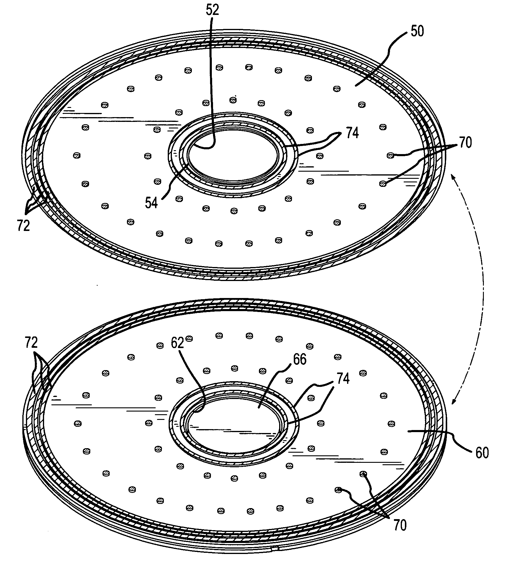
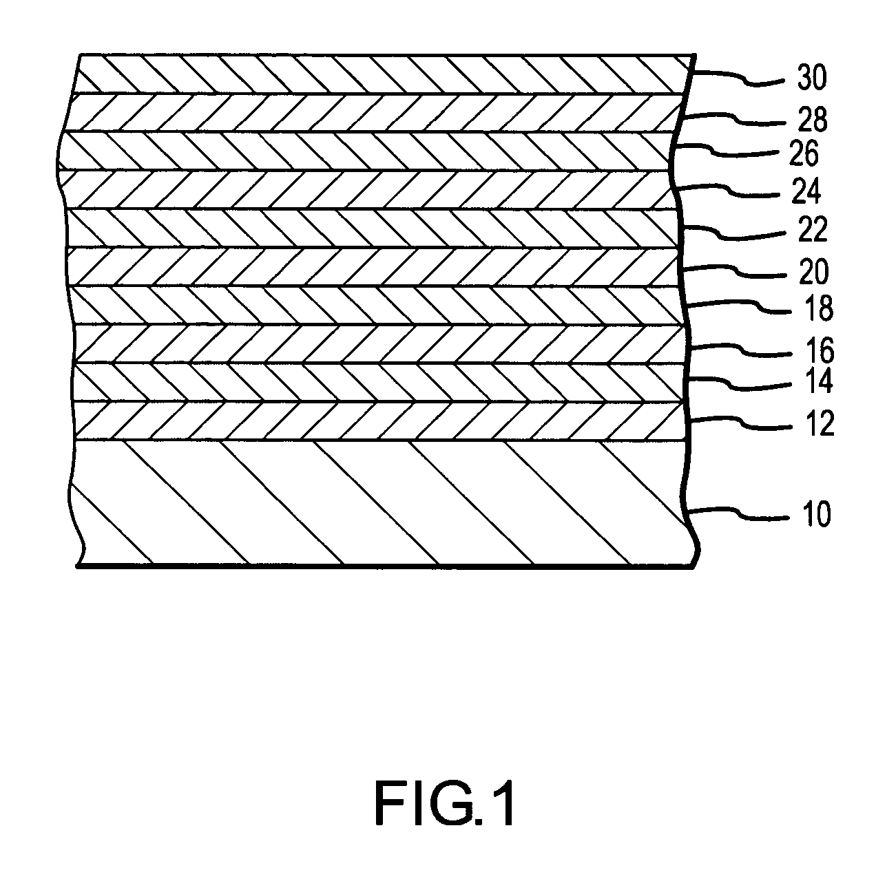
[0009] The first plate and the second plate may be disposed in a spaced relationship and interconnected by at least one first annular wall. “Annular” in relation to the first annular wall and other components described herein as being “annular” herein, means that the particular structure extends a full 360 degrees about a common reference point, and thereby does not limit the particular structure to having a circular configuration. This first annular wall may surround at least part of a flow path through the MEMS flow module so as to define at least one “radial” seal (e.g., to at least reduce the potential for fluid escaping from the MEMS flow module through the space between the first and second plates). Using multiple, radially spaced first annular walls would thereby provide redundant radial seals. The first and second flow ports would then be located inwardly of each such first annular wall in a radial or lateral dimension. One or more additional structural interconnections of any appropriate size, shape, configuration, and arrangement may exist between the first and second plates to provide a desired degree of rigidity for the MEMS flow module. The first plate could also be formed directly on or disposed in interfacing relation with the second plate to increase the rigidity of the MEMS flow module as well, with the first and second flow ports being fluidly interconnected in any appropriate manner.
[0014] The second plate and the third plate may be disposed in a spaced relationship and interconnected by at least one second annular wall. This second annular wall may surround at least part of a flow path through the MEMS flow module so as to define at least one “radial” seal (e.g., to at least reduce the potential for fluid escaping from the MEMS flow module through the space between the second and third plates in the radial or lateral dimension). Using multiple, radially spaced second annular walls would thereby provide redundant radial seals. The second and third flow ports would then be located inwardly of each such second annular wall in a radial or lateral dimension. One or more additional structural interconnections of any appropriate size, shape, configuration, and arrangement may exist between the second and third plates to provide a desired degree of rigidity for the MEMS flow module. The second plate could also be formed directly on or disposed in interfacing relation with a “stationary portion” of the third plate (e.g., any portion of the third plate that does not move to any significant degree to accommodate movement of the regulator) in order to increase the rigidity of the MEMS flow module as well.
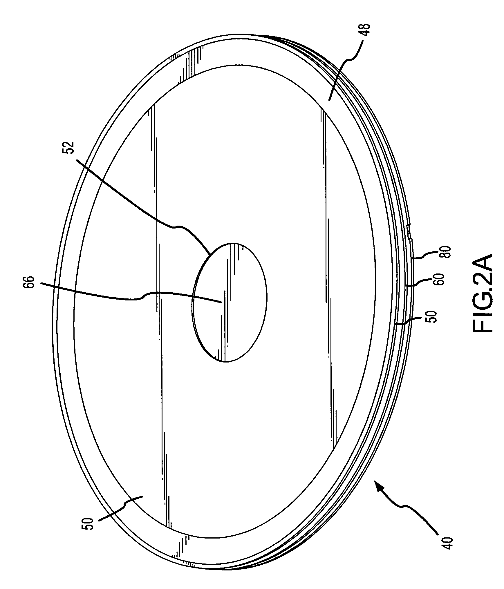
[0016] As the magnitude of the noted pressure differential is reduced, the third plate may move back at least towards its initial / static position (e.g., wherein the regulator is substantially coplanar with the second plate) using the elastic or spring forces that were created and stored within the third plate by flexing away from the second plate. That is, the internal stresses caused by flexing the third plate of the MEMS flow module away from the second plate may provide a restoring force that at least contributes to moving the regulator back toward or all the way back to its static or home position.
[0022] The above-noted movement of the regulator in response to a pressure differential across the MEMS flow module is itself subject to a number of characterizations. One is that the regulator may be operative to move in at least two different directions. For instance, the regulator may move at least generally away from the first plate, which may allow for increasing the volume of a flow channel associated with and downstream of the first flow port. The regulator may also move at least generally toward the first plate, which may allow for reducing the volume of this same flow channel and / or substantially restricting or impeding a flow through the first flow port.
[0025] Each first flow port may further include an associated flow-restricting structure. This flow-restricting structure may extend from the first plate and proceed toward the regulator, and terminate prior to reaching the regulator. The flow-restricting structure may reduce the size of a space through which a flow must progress after passing through the first flow port, and the size of which is determined at least in part by the position of the regulator. In one embodiment, the flow-restricting structure terminates prior to reaching the regulator. The flow-restricting structure may be of any appropriate form, such as an annular wall or a plurality of flow-restricting segments that are appropriately spaced from each other. Alternatively, such a flow-restricting structure may extend from the regulator toward the first plate. Another option would be for the regulator to include a plug that is at least aligned with the first flow port. Such a plug could simply be disposed “over” the first flow port, or such a plug could actually extend into the first flow port (preferably remaining spaced therefrom).

Problems solved by technology

High internal pressure within the eye can damage the optic nerve and lead to blindness.
There are a number of issues with implants of this type.

Method used


Image

  • MEMS flow module with piston-type pressure regulating structure
  • MEMS flow module with piston-type pressure regulating structure
  • MEMS flow module with piston-type pressure regulating structure

Examples


Embodiment Construction

[0066] The present invention will now be described in relation to the accompanying drawings that at least assist in illustrating its various pertinent features. Generally, the devices described herein are microfabricated. There are a number of microfabrication technologies that are commonly characterized as “micromachining,” including without limitation LIGA (Lithographie, Galvonoformung, Abformung), SLIGA (sacrificial LIGA), bulk micromachining, surface micromachining, micro electrodischarge machining (EDM), laser micromachining, 3-D stereolithography, and other techniques. Hereafter, the term “MEMS device”, “microfabricated device,” or the like means any such device that is fabricated using a technology that allows realization of a feature size of 10 microns or less.

[0067] Surface micromachining is currently the preferred fabrication technique for the various devices to be described herein. One particularly desirable surface micromachining technique is described in U.S. Pat. No. ...


PUM


Abstract

Various embodiments of MEMS flow modules that regulate flow or pressure by the axial movement of a flow regulating or controlling structure are disclosed. One such MEMS flow module (40) has a regulator (66) that is aligned with and spaced from a first flow port (52) through a first plate (50). The regulator (66) is structurally interconnected with a flexible third plate (80). When the regulator (66) experiences at least a certain differential pressure, the regulator (66) moves at least generally axially away from the first plate (50) by a flexing of the third plate (80) at least generally away from the first plate (50). Increasing the spacing between the regulator (66) and the first plate (50) accommodates an increased flow or flow rate through the MEMS flow module (40).

Description

FIELD OF THE INVENTION [0001] The present invention generally relates to the field of microfabricated devices and, more particularly, to a MEMS flow module that uses a piston-type structure to provide at least a pressure regulation function. BACKGROUND OF THE INVENTION [0002] High internal pressure within the eye can damage the optic nerve and lead to blindness. There are two primary chambers in the eye—an anterior chamber and a posterior chamber that are generally separated by a lens. Aqueous humor exists within the anterior chamber, while vitreous humor exists in the posterior chamber. Generally, an increase in the internal pressure within the eye is caused by more fluid being generated within the eye than is being discharged by the eye. The general consensus is that it is the fluid within the anterior chamber of the eye that is the main contributor to an elevated intraocular pressure. [0003] One proposed solution to addressing high internal pressure within the eye is to install a...

Claims


Application Information

Patent Timeline
Patent Type & Authority Applications(United States)
IPC IPC(8): A61M5/00
CPCA61F9/00781A61M5/16813A61M39/24A61M2205/0244A61M2205/04B82Y30/00
Inventor RODGERS, M. STEVENSNIEGOWSKI, JEFFRY J.
Owner BECTON DICKINSON & CO
Features
  • Generate Ideas
  • Intellectual Property
  • Life Sciences
  • Materials
  • Tech Scout
  • Unparalleled Data Quality
  • Higher Quality Content
  • 60% Fewer Hallucinations
Learn More