
Control for an automatic plumbing device

a technology for plumbing devices and control devices, applied in the field of control devices for plumbing devices, can solve the problems of failure of the plumbing device to trigger operation, waste of water and user annoyance, and easy false triggering of object detection systems, so as to reduce the false triggering of the device

Active Publication Date: 2006-09-21
MASCO CANADA
View PDF9 Cites 33 Cited by
  • Summary
  • Abstract
  • Description
  • Claims
  • Application Information

AI Technical Summary

Benefits of technology

[0005] An automatic plumbing device according to the present invention provides improved object detection in a desired volume.
[0009] The automatic plumbing device according to the present invention provides a more tailored detection region and reduces false triggering of the device caused by reflections.

Problems solved by technology

Disadvantageously, this may result in the failure of the plumbing device to trigger operation until the user's hand is directly under the faucet.
The object detection systems also are prone to false triggering as a result of unwanted reflections off of surrounding objects, such as a sink, or off the water stream itself.
If the reflection off the water stream is not avoided, the solenoid valve may become locked-on, thus resulting in a waste of water and annoyance to the user.

Method used


Image

  • Control for an automatic plumbing device
  • Control for an automatic plumbing device
  • Control for an automatic plumbing device

Examples


Embodiment Construction

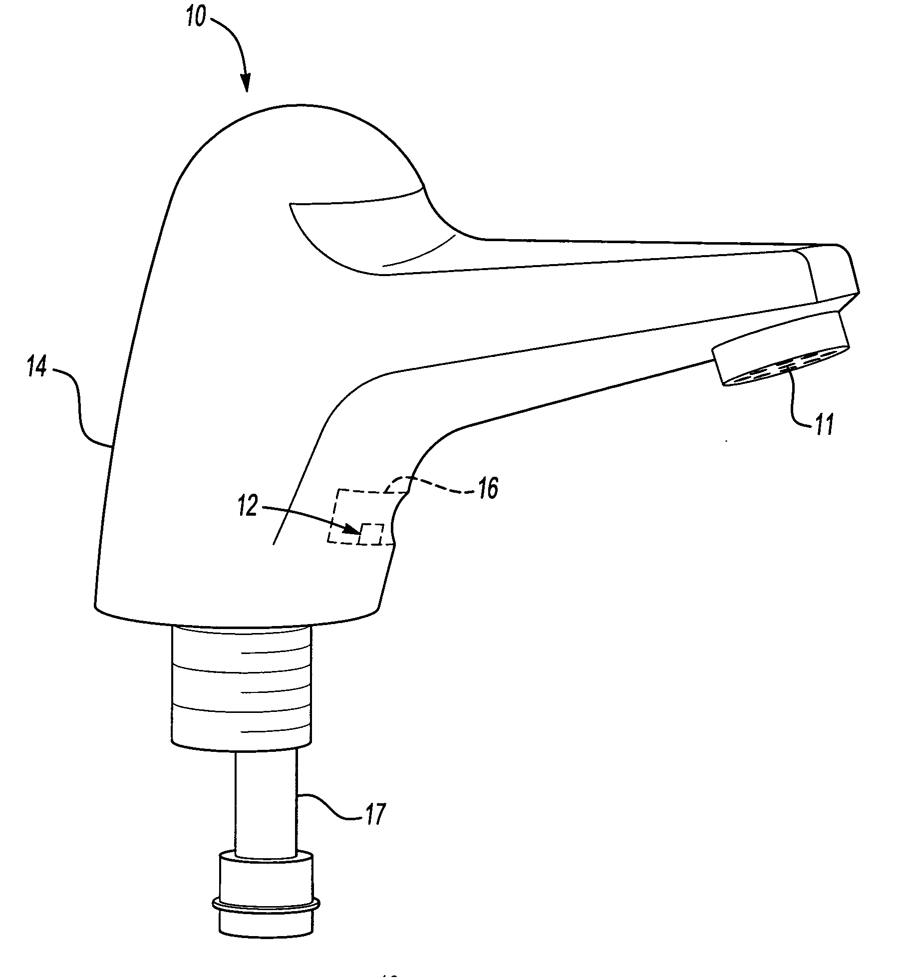
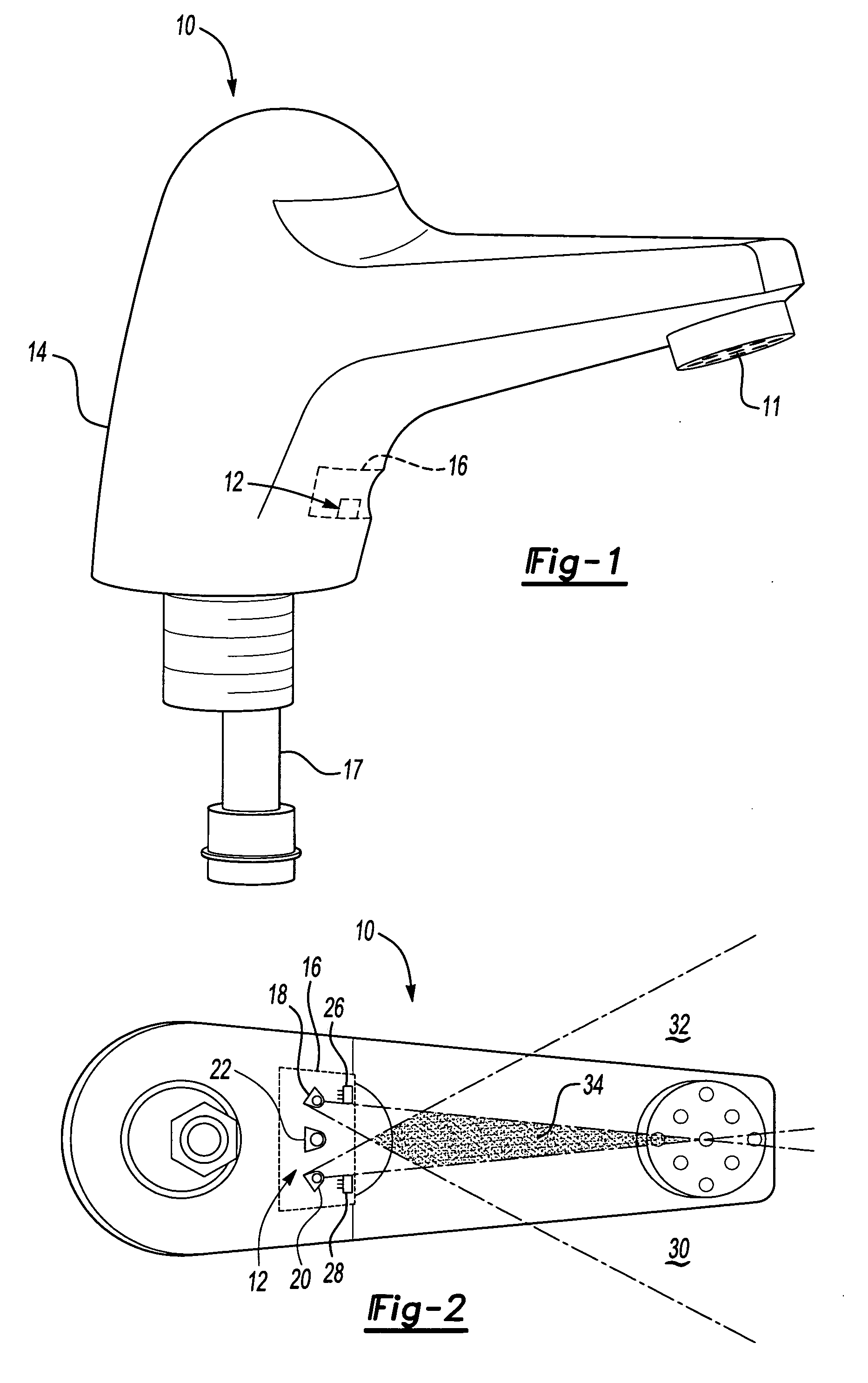
[0016] Referring to FIG. 1, a water faucet 10 adapted with an object detection system 12 according to the present invention is illustrated. Although the object detection system 12 is shown and described in terms of a water faucet 10, it should be understood that other plumbing devices, including but not limited to toilets and showers, may employ the configuration disclosed herein.

[0017] The water faucet 10 defines a spout section 11 and a base section 14. The base section 14 includes a housing 16 for housing the object detection system 12 of the present invention. A pipe 17 communicates a liquid, such as water, through the base section 14 to the spout section 11 where the water exits the water faucet 10.

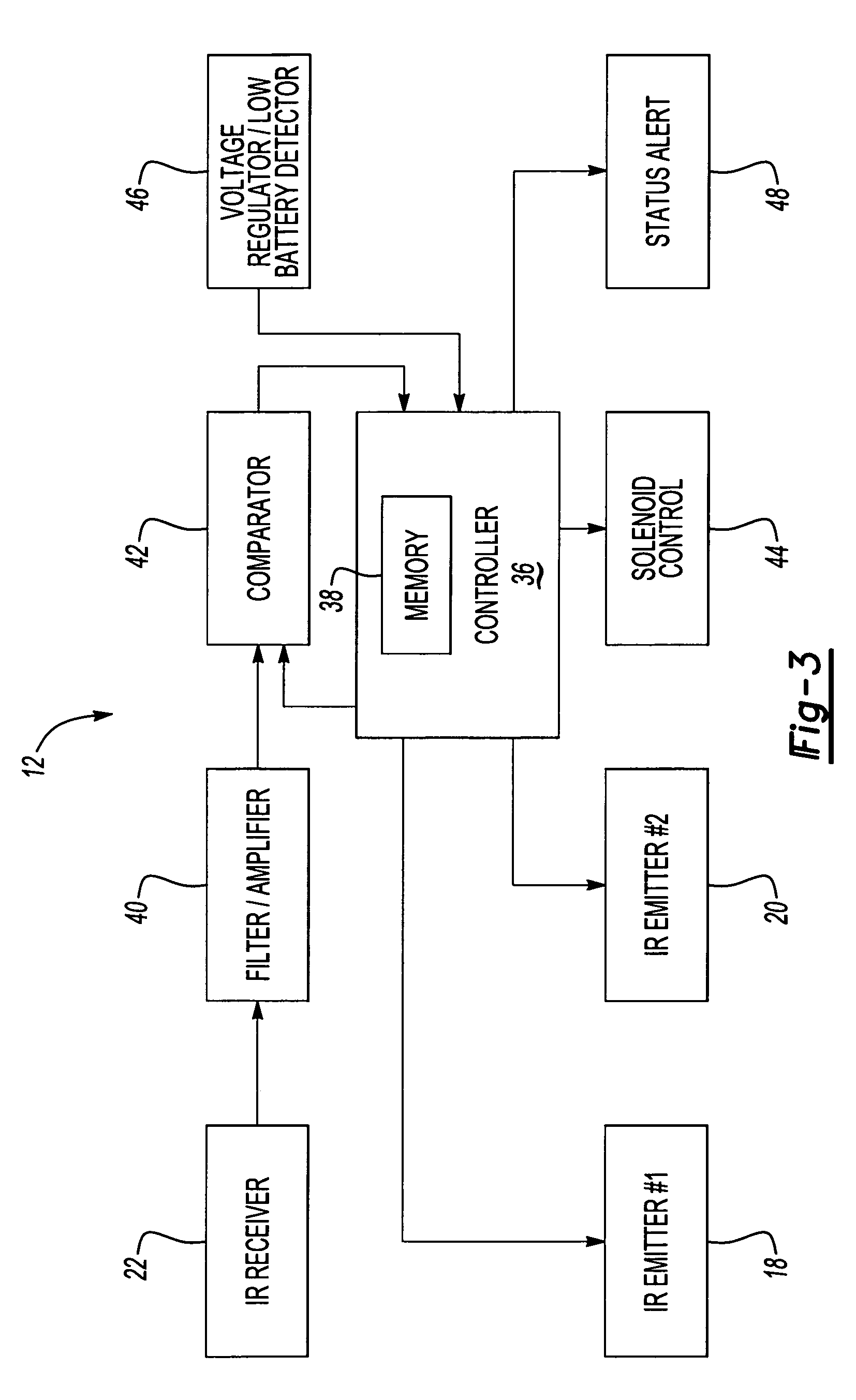
[0018] Referring to FIG. 2, the configuration of the object detection system 12 within the housing 16 of the water faucet 10 is illustrated. The housing 16 houses an IR emitter 18 (on the top as shown in FIG. 2), an IR emitter 20 (on the bottom), and an IR receiver 22 (in the cente...


PUM


Abstract

A plumbing device uses electronic control circuitry with two infrared emitters and one infrared receiver to detect objects in a particular region of space. In one embodiment, detection of an object using both sensors (in sequential scans) results in the plumbing device turning on. When no object has been detected for a certain amount of time, the plumbing device is turned off. Also, when the plumbing device has run for another certain amount of time, the plumbing device is turned off regardless of whether an object is still being detected. In another embodiment, the output of the IR emitters is partially blocked by one or more mask elements to tailor the region that is covered by both IR emitters and, hence, the region that triggers the opening of the plumbing device valve.

Description

BACKGROUND OF THE INVENTION [0001] The present invention relates to controls for plumbing devices, and more particularly to plumbing devices automatically triggered by infrared-based object detection. [0002] Object detection systems that use infrared (IR) signals to trigger plumbing device operation, such as operation of an automatic faucet, are known. Typically, these systems utilize a single IR emitter and an IR detector to control fluid flow based upon object detection within a defined region. A control activates the IR emitter and then monitors the IR detector for reflections of infrared light from objects (such as a user's hands) that are sensed and used to determine whether to activate or deactivate a solenoid valve. [0003] The object detection systems are typically designed and implemented integral to the plumbing device. Disadvantageously, this may result in the failure of the plumbing device to trigger operation until the user's hand is directly under the faucet. The object...

Claims


Application Information

Patent Timeline
Patent Type & Authority Applications(United States)
IPC IPC(8): E03C1/05
CPCE03C1/057
Inventor VINCENT, RAYMOND A.
Owner MASCO CANADA
Learn More