
Micro liquid cooling device

a liquid cooling and micro-liquid technology, applied in the direction of cooling/ventilation/heating modification, semiconductor device details, semiconductor/solid-state device details, etc., can solve the problem of reducing the overall dimension of the heat dissipating device, and reducing the efficiency of the device. the effect of vibration and nois

Inactive Publication Date: 2006-09-21
INVENTEC CORP
View PDF9 Cites 12 Cited by
  • Summary
  • Abstract
  • Description
  • Claims
  • Application Information

AI Technical Summary

Benefits of technology

The present invention provides a micro liquid cooling device that reduces vibration and noise, improves reliability, and reduces space required and cost. The device includes a radiator, thermal conductor, actuator, and a circular path for circulating a liquid coolant. The actuator has a thin film sealed with a high ductility inner aperture and a smaller outer aperture, and the inner aperture of the inlet diffusion port is larger than the outer aperture of the outlet diffusion port. The thin film can be a high polymer film such as polyethylene, and the magnetic body can be a permanent magnet. The device can be controlled by the design of the inlet and outlet diffusion ports to improve reliability, reduce vibration and noise, and eliminate the need for moveable check valves. The present invention eliminates many prior-art drawbacks and improves the applicability of micro liquid cooling devices.

Problems solved by technology

The radiator employed in such method of heat dissipation, however, requires a sufficient heat dissipating surface to be effective.
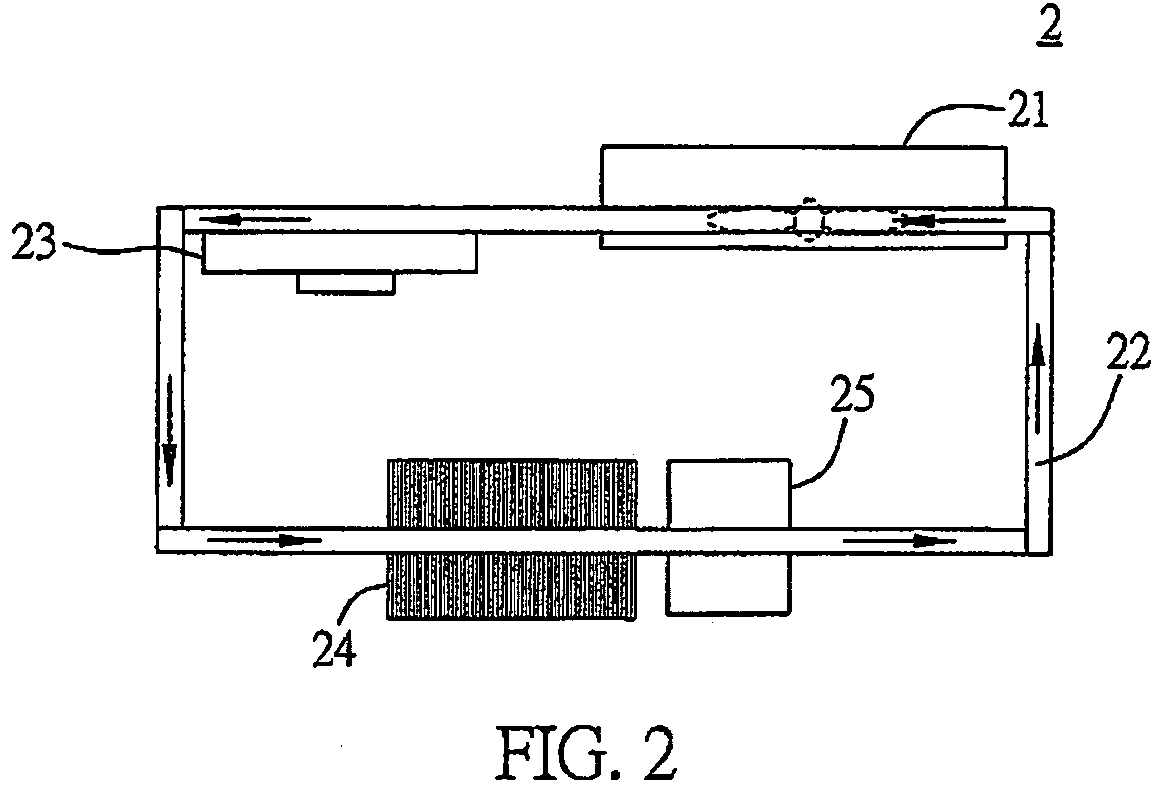
Moreover, the overall dimensions of the heat dissipating device are further increased after installation of the fan, such that the device cannot be used in a portable electronic device such as a notebook computer.
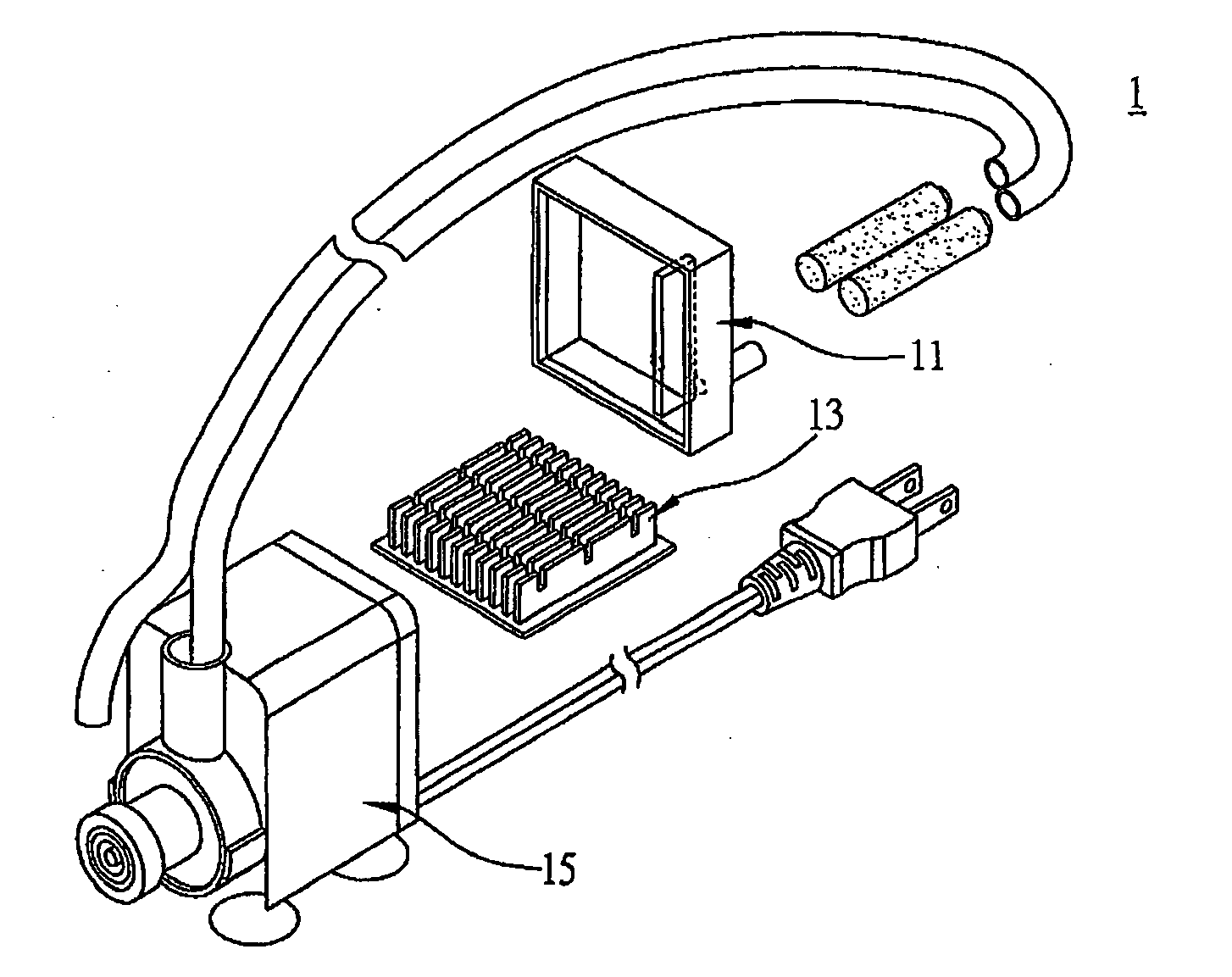
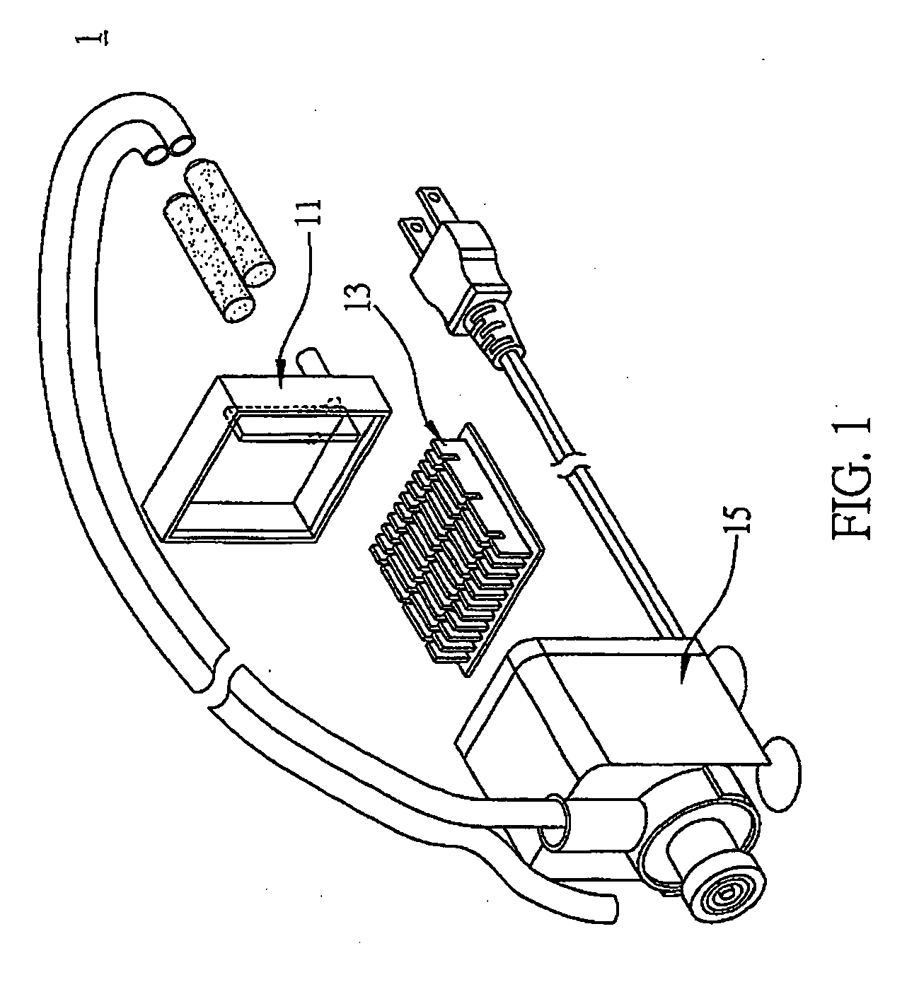
However, as it employs the mechanical pump 15 to circulate the liquid coolant, the overall dimensions are excessively large, such that the method is not applicable to a portable electronic device such as a notebook computer.
However, as the movable check valves need to be provided in the pipes, an extra cost is incurred and extra space is required.
Moreover, vibration and noise are produced as the movable check valves open or close, so as to reduce the reliability of actuation of the liquid coolant and applicability to electronic devices.

Method used


Image

  • Micro liquid cooling device
  • Micro liquid cooling device
  • Micro liquid cooling device

Examples


Embodiment Construction

[0027] Referring to FIG. 3, the present invention proposes a micro liquid cooling device 3 for dissipating heat generated by at least a heat-producing element. The micro liquid cooling device 3 comprises a micro actuator 31, a circular path 32, a thermal conductor 33, a radiator 34, and a storage container 35. The circular path 32 serves to circulate a liquid coolant. The thermal conductor 33 serves to absorb heat from the heat-producing element. The actuator 31 serves to circulate and supply the liquid coolant to the thermal conductor 33 via the circular path 32. The radiator 34 is used to dissipate heat transferred to the liquid coolant. Furthermore, a fan can be provided to improve the heat dissipation efficiency, and the storage container 35 can serve to supply the liquid coolant.

[0028] The actuator 31 is provided with a cavity 311 sealed with a thin film 312, an inlet diffusion port 315 connected to the cavity 31, an outlet diffusion port 316 connected to the cavity 311, a mag...


PUM


Abstract

A micro liquid cooling device including a radiator, a thermal conductor, an actuator, and a circular path is proposed. The actuator includes a cavity sealed with a thin film, an inlet diffusion port connected to the cavity, an outlet diffusion port connected to the cavity, a magnetic body connected to the thin film, and a pole acting on the magnetic body, such that circulation of a liquid coolant in the circular path can be effected. By such design of the actuator, vibration and noise can be reduced and reliability can be improved, and thus problems caused by the use of a prior-art technique which employs a piezoelectric pump as an actuation source for the liquid coolant can be solved.

Description

FIELD OF THE INVENTION [0001] The present invention relates to a design for a heat dissipating device, and more particularly, to a micro liquid cooling device applicable to a heat-producing element such as a semiconductor device for heat dissipation. BACKGROUOND OF THE INVENTION [0002] Along with the developments in semiconductor technology, various electronic devices are progressively being miniaturized. For example, the working temperature of a heat-producing element such as a microprocessor is gradually increasing. Thus, the development of a heat dissipating device for heat dissipation of the heat-producing element is a key factor to provide stable operation of the electronic device. [0003] Referring to heat dissipation of a central processing unit of a computer, a heat dissipating device comprising a radiator and a fan is normally employed. The radiator, typically made of aluminum or copper materials, is attached to a surface of the central processing unit, such that heat genera...

Claims


Application Information

Patent Timeline
Patent Type & Authority Applications(United States)
IPC IPC(8): H05K7/20
CPCH01L23/473H01L2924/0002H01L2924/00
Inventor CHIU, CHAUCERCHEN, YONG-GUO
Owner INVENTEC CORP
Learn More