High-power microwave system employing a phase-locked array of inexpensive commercial magnetrons

a phaselocked array, commercial magneton technology, applied in the direction of transit tube circuit elements, amplifiers with transit-time effect, plasma technique, etc., can solve the problems of reducing the efficiency of the system, etc., to achieve the effect of facilitating the coherent combination

Inactive Publication Date: 2006-09-21
L 3 COMM CORP
View PDF5 Cites 23 Cited by
  • Summary
  • Abstract
  • Description
  • Claims
  • Application Information

AI Technical Summary

Benefits of technology

[0016] This invention solves these problems by adding, for the first time, a secondary coupling path between each of a plurality of magnetron tube output pairs whereby a portion of the output energy from a first magnetron tube is injected into a second magnetron tube and a portion of the output energy from the second magnetron tube is similarly injected into the first magnetron tube. The resulting pair-wise cross-injection of microwave energies brings e

Problems solved by technology

A single magnetron tube operating continuously is presently subject to practical output power limits of about 1 MW, which can be attained only with a very large and expensive device supported by large and expensive external cooling systems.
Moreover, the power losses in power circulators 22-24 are also a significant burden in some applications.
Circulator 36 must be fabricated to handle the primary output power from magnetron tube 38 and is generally disadvantageously inefficient.
Available solutions to the magnetron phase-locking problem, such as the external

Method used


Image

  • High-power microwave system employing a phase-locked array of inexpensive commercial magnetrons
  • High-power microwave system employing a phase-locked array of inexpensive commercial magnetrons
  • High-power microwave system employing a phase-locked array of inexpensive commercial magnetrons

Examples


Embodiment Construction

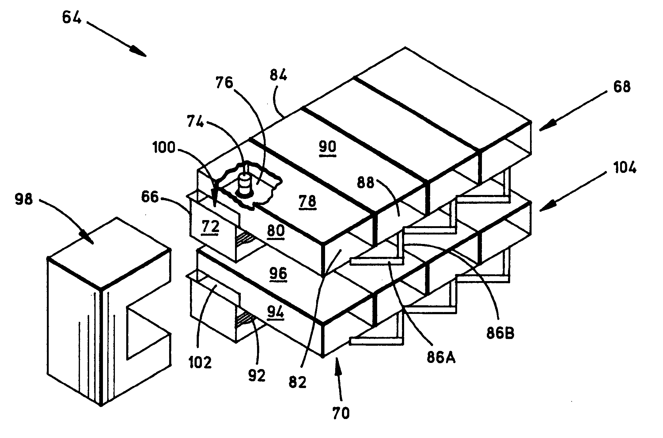
[0033]FIG. 4 is a perspective view of an illustrative phase-locked magnetron array embodiment 64 of this invention having eight magnetron tubes, exemplified by the magnetron tube 66, disposed in a two-dimensional array, with rows exemplified by the row 68 that includes magnetron tube 66, and columns exemplified by the column 70 that includes magnetron tube 66. Each magnetron tube may be appreciated with reference to the following description of magnetron tube 66, which includes a body 72, an output antenna 74 extending into an output cavity 76, which is coupled to a primary coupling waveguide 78, having a sidewall 80. The microwave energy produced at anode antenna 74 is coupled from output cavity 76 and radiated into free space at the primary aperture 82 of primary coupling waveguide 78 to create a radiated microwave field in the usual manner.

[0034] The operation of any horizontally-adjacent pair of magnetron tubes can be appreciated with reference to the following discussion of th...


PUM


Abstract

A high-power microwave generator employing a plurality of inexpensive commercial magnetron tubes cross-coupled by means of a secondary coupling path between each magnetron output pair, whereby a portion of the output energy from a first magnetron tube is injected into a second magnetron tube and a portion of the output energy from the second magnetron tube is similarly injected into the first magnetron tube. The resulting cross-injection of microwave energies brings the respective magnetron tube pair into a phase-lock sufficiently stable to permit coherent combination of their outputs for many high-power microwave applications, such as directed energy weapon systems. The magnetron phase-locking system requires no external components other than the secondary coupling paths of this invention.

Description

BACKGROUND OF THE INVENTION [0001] 1. Field of the Invention [0002] This invention relates generally to high-power microwave generators and more particularly to high-power microwave systems employing a phase-locked array of inexpensive commercial magnetrons. [0003] 2. Description of the Related Art [0004] The conventional magnetron (herein also denominated “magnetron tube”) is a well-known and very efficient device used to convert stored electrical energy into microwave-frequency alternating currents. Magnetron operating principles have been known since at least 1921 and magnetrons have been used in extensively in microwave radars since the first pulsed resonant cavity magnetron (3 GHz) was developed by the British in 1940. Today, inexpensive mass-produced magnetrons (herein also denominated “commercial magnetrons”) can be found in every home possessing a microwave oven. [0005] A typical single-body magnetron tube known in the art is a coaxial vacuum device consisting essentially of...

Claims


Application Information

Patent Timeline
IPC IPC(8): H05H7/00
CPCH03F3/54H03F3/602H03F2200/451H05H1/46
Inventor ACHENBACH, ROBERT PARKERLERMA, ALBERT
Owner L 3 COMM CORP
Why Eureka
Try Eureka