Step-down switching regulator

a switching regulator and step-down technology, applied in the direction of electric variable regulation, process and machine control, instruments, etc., can solve the problems of reducing efficiency at a light load time, difficulty in interrupting a current backflow by turning off the switching device swb, etc., to achieve the effect of quick change of output voltage and improved efficiency

Inactive Publication Date: 2006-09-21
RICOH ELECTRONIC DEVICES CO LTD
View PDF5 Cites 33 Cited by
  • Summary
  • Abstract
  • Description
  • Claims
  • Application Information

AI Technical Summary

Benefits of technology

[0016] According to a step-down switching regulator according to one embodiment of the present invention, when a change in a set voltage is detected, the operation of causing a switching controller circuit part to turn off a second switching element due to detection of a reverse current is stopped for a predetermined period of time, and after the predetermined period is over, the switching controller circuit part is caused to turn off the second switching element upon detection of the reverse current. This configuration makes it possible to change output voltage swiftly, and to improve efficiency at a light load time in particular.

Problems solved by technology

However, in the synchronous rectification step-down switching regulator capable of changing output voltage, it is necessary to change the output voltage swiftly even at a light load time, so that it is difficult to interrupt a backflow of current by turning OFF the switching device SWb upon detection of the backflow of current.
This causes the problem of reduced efficiency at a light load time.

Method used


Image

  • Step-down switching regulator
  • Step-down switching regulator
  • Step-down switching regulator

Examples


first embodiment

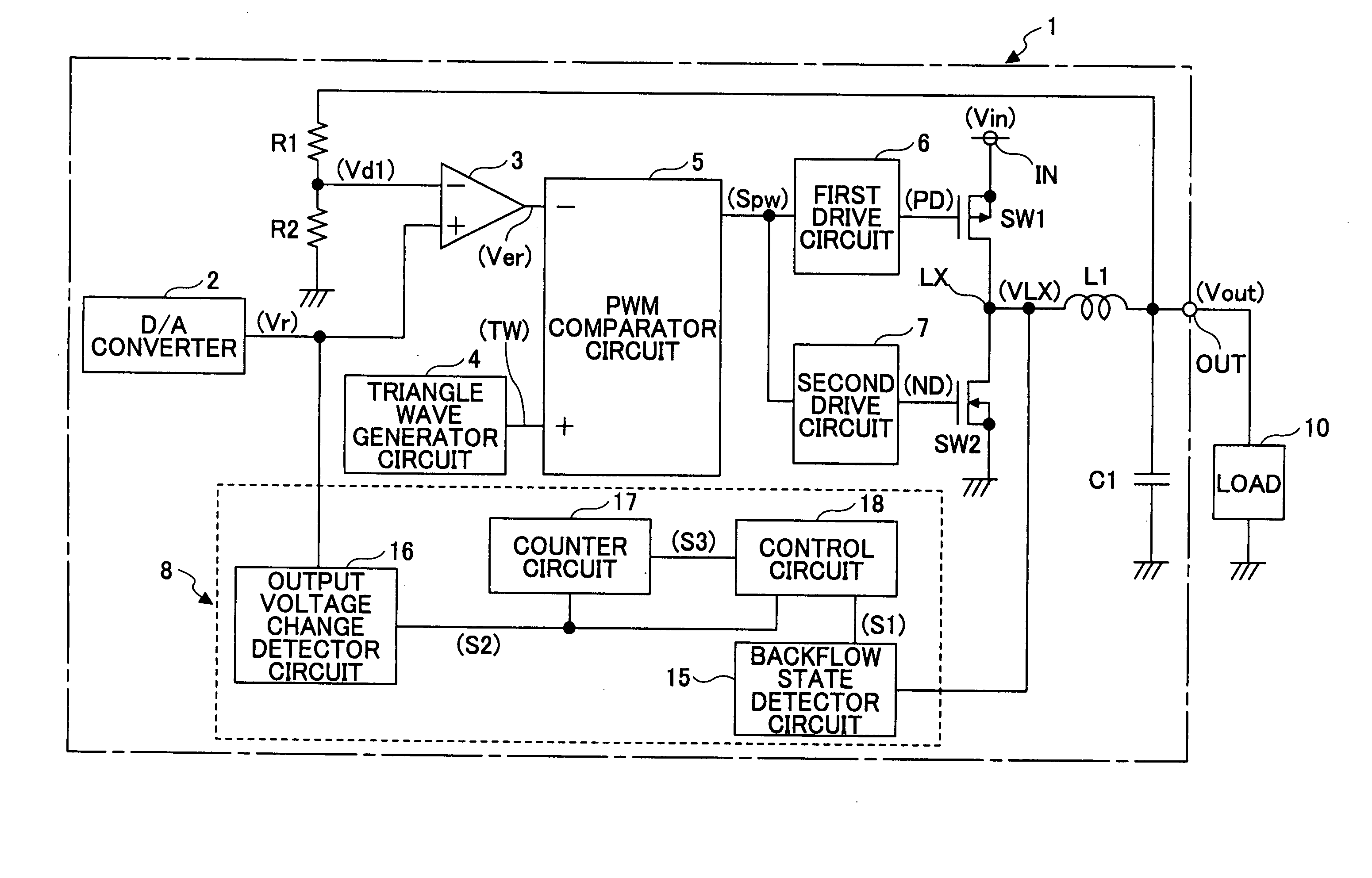
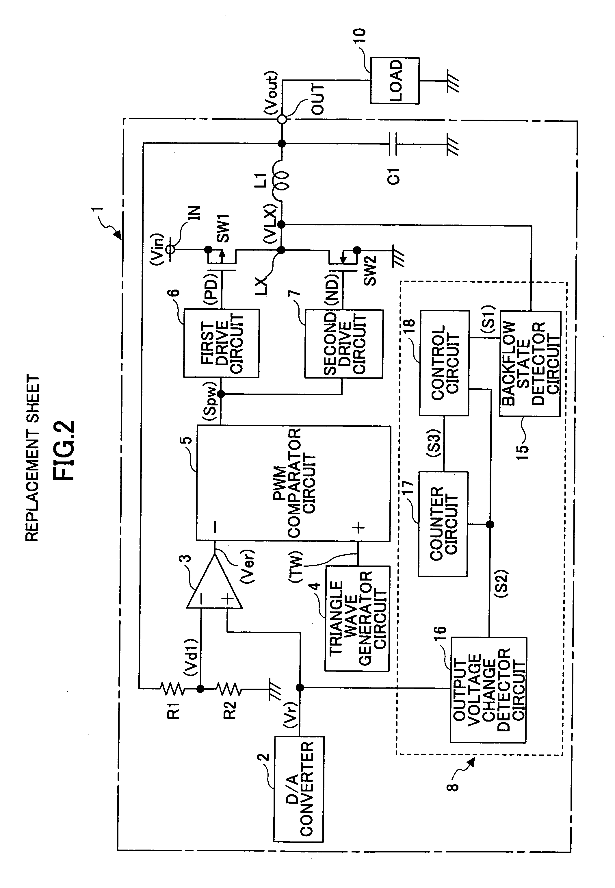
[0024]FIG. 2 is a circuit diagram showing a step-down switching regulator 1 according to a first embodiment of the present invention.

[0025] Referring to FIG. 2, according to the switching regulator 1, a supply voltage supplied from a DC power supply (not graphically illustrated) such as a battery is input to an input terminal IN as an input voltage Vin, and a predetermined constant voltage is generated from the input voltage Vin and output from an output terminal OUT to a load 10 as an output voltage Vout.

[0026] The switching regulator 1 includes a switching device SW1 formed of a PMOS transistor, a switching device SW2 for synchronous rectification formed of an NMOS transistor, an inductor L1 and a capacitor C1 for smoothing, and resistors R1 and R2 for output voltage detection. The switching device SW1 performs output control of the input voltage Vin input to the input terminal IN. The resistors R1 and R2 generate a divided voltage Vd1 by dividing the voltage Vout output from th...

second embodiment

[0039] According to the above-described first embodiment, the output voltage Vout is changed by changing the value of the reference voltage Vr. Meanwhile, according to a second embodiment of the present invention, the reference voltage Vr is constant while the divided voltage Vd1 is changed by an external analog-level signal. In this case, the reverse current detector circuit part 8 of FIG. 2 may detect a change in the setting of the output voltage Vout by detecting the analog-level signal. This configuration is employed in the second embodiment.

[0040]FIG. 4 is a circuit diagram showing a step-down switching regulator 1a according to the second embodiment. In FIG. 4, the same elements as those of FIG. 2 are referred to by the same numerals, and a description thereof is omitted. With respect to FIG. 4, a description is given of the differences from FIG. 2.

[0041] In FIG. 4, the differences from FIG. 2 are as follows. The D / A converter 2 of FIG. 2 is replaced by a reference voltage g...

third embodiment

[0048] A description is given of a third embodiment of the present invention.

[0049] In each of the first and second embodiments, the switching device SW1 may turn ON to output the input voltage Vin while the output voltage Vout is set to be higher than or equal to the input voltage Vin, and / or the gate-source voltage of the switching device SW1 may be reduced to limit output current when more current than expected flows from the output terminal OUT because of occurrence of an abnormality such as short-circuiting of the output terminal OUT. This configuration is employed in the third embodiment.

[0050]FIG. 5 is a circuit diagram showing a step-down switching regulator 1b according to the third embodiment. FIG. 5 shows a configuration based on the configuration of FIG. 2 by way of example. In FIG. 5, the same elements as those of FIG. 2 are referred to by the same numerals, and a description there of is omitted. With respect to FIG. 5, a description is given of the differences from F...


PUM


Abstract

A step-down switching regulator is disclosed that includes a first switching element, a smoothing circuit part including an inductor and a second switching element for synchronous rectification, a switching controller circuit part, and a reverse current detector circuit part that detects a reverse current flowing from the inductor to the second switching element and interrupts the reverse current by causing the switching controller circuit part to turn off the second switching element upon detection of the reverse current. Detecting a change in a set voltage, the reverse current detector circuit part stops, for a predetermined period of time, the operation of causing the switching controller circuit part to turn off the second switching element due to detection of the reverse current, and after the predetermined period of time is over, causes the switching controller circuit part to turn off the second switching element upon detection of the reverse current.

Description

BACKGROUND OF THE INVENTION [0001] 1. Field of the Invention [0002] The present invention relates generally to step-down switching regulators of a synchronous rectification type capable of changing output voltage, and more particularly to a step-down switching regulator having a circuit to interrupt a backflow of current from an inductor for smoothing to a switching device for synchronous rectification by turning off the switching device upon detection of the backflow of current. [0003] 2. Description of the Related Art [0004]FIG. 1 is a circuit diagram showing a conventional step-down switching regulator 100. [0005] According to the switching regulator 100, a supply voltage supplied from a DC power supply such as a battery is input to an input terminal IN as an input voltage Vin, and a predetermined constant voltage is generated from the input voltage Vin and output from an output terminal OUT to a load 111 as an output voltage Vout. [0006] The switching regulator 100 includes a sw...

Claims


Application Information

Patent Timeline
Patent Type & Authority Applications(United States)
IPC IPC(8): G05F1/00
CPCH02M3/157H02M3/1588H02M2001/0009H02M2001/0025Y02B70/1466H02M1/0009H02M1/0025Y02B70/10
Inventor SHIMIZU, SHINYAMATSUO, MASAHIRO
Owner RICOH ELECTRONIC DEVICES CO LTD
Why Eureka
Try Eureka