
Heat receiving member, heat receiving device and electronic equipment

a heat receiving device and heat generating member technology, applied in the field of heat receiving members, can solve the problems of inability to efficiently receive heat from the heat generating member, increase in the size of electronic equipment incorporating the heat sink, and inability to meet the needs of cooling/ventilation/heating modifications, etc., and achieve the effect of efficient heat reception

Inactive Publication Date: 2006-09-21
FUJITSU LTD
View PDF31 Cites 34 Cited by
  • Summary
  • Abstract
  • Description
  • Claims
  • Application Information

AI Technical Summary

Benefits of technology

[0009] An object of the present invention, which is conceived under such circumstances, is to provide a heat receiving member which is capable of efficiently receiving heat from a heat generating member by bringing the heat generating member into direct contact with a coolant, to provide a heat receiving device including such a heat generating member and a heat receiving member, and to provide an electronic equipment including a printed circuit board on which a heat generating member is mounted.
[0010] A heat receiving member according to the present invention includes a coolant passage for flowing a coolant for receiving heat generated at a heat generating member. The heat receiving member is formed with an opening for fitting the heat generating member so that the heat generating member comes into contact with the coolant. In the heat receiving member of the present invention, the heat generating member comes into contact with the coolant in the coolant passage. Therefore, an obverse surface of the heat generating member comes into direct contact with the coolant. As a result, the heat transfer path between the heat generating member and the coolant becomes shorter, and hence, the heat resistance is reduced, so that the heat receiving efficiency is enhanced.
[0012] A heat receiving device according to the present invention comprises a heat generating member at which heat is generated, and a heat receiving member including a coolant passage for flowing a coolant for receiving heat from the heat generating member. The heat receiving member is formed with an opening, and the heat generating member is fitted in the opening to come into contact with the coolant. In the heat receiving device of the present invention, the heat generating member fitted in the opening of the heat receiving member comes into direct contact with the coolant. Therefore, the heat transfer path between the heat generating member and the coolant becomes shorter, and hence, the heat resistance is reduced, so that the heat receiving efficiency is enhanced.
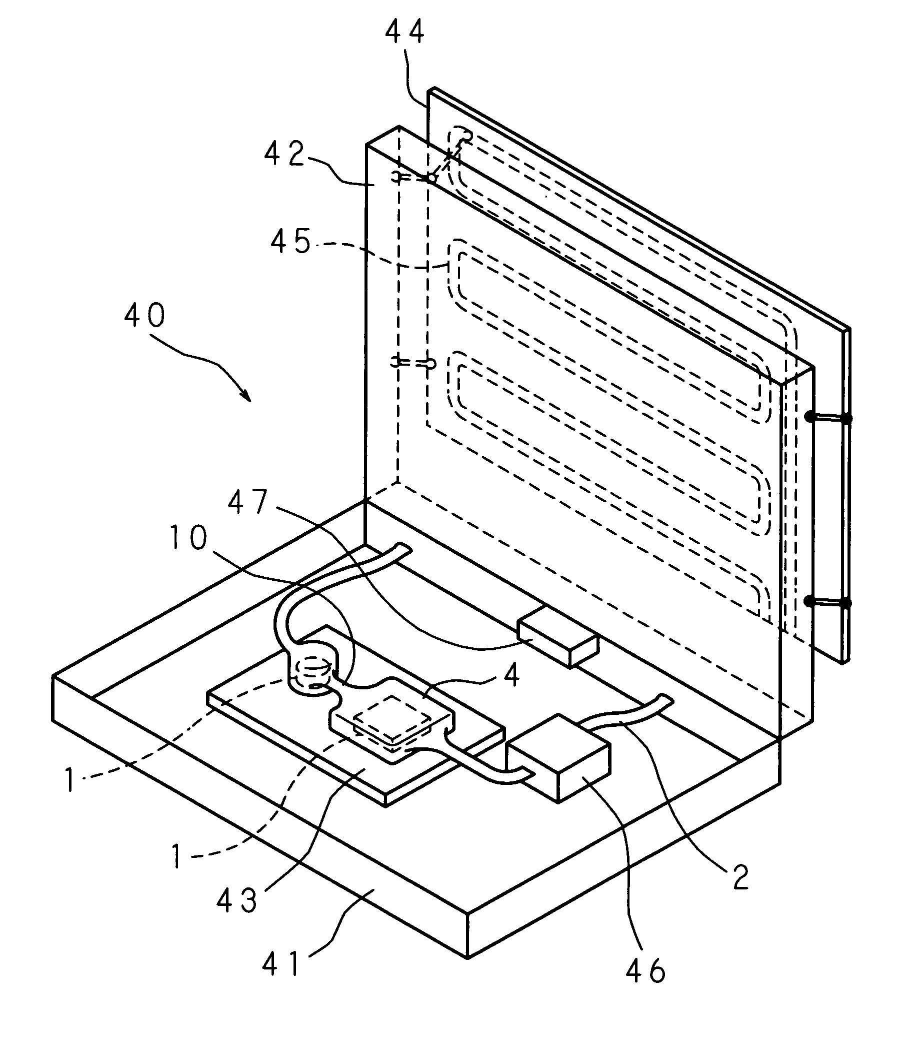
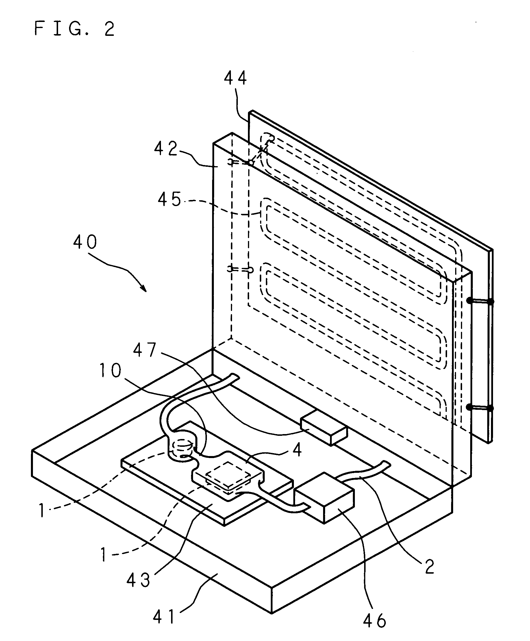
[0014] An electronic equipment according to the present invention comprises a heat receiving member including a coolant passage for flowing a coolant for receiving heat generated at a heat generating member, and a printed circuit board on which the heat generating member is mounted. The heat receiving member is formed with an opening, and the heat generating member is fitted in the opening to come into contact with the coolant. In the electronic equipment of the present invention, the heat generating member such as an electronic component mounted on the printed circuit board is fitted into the opening of the heat receiving member to come into direct contact with the coolant. Therefore, the heat transfer path between the heat generating member and the coolant becomes shorter, and hence, the heat resistance is reduced, so that the heat receiving efficiency is enhanced.

Problems solved by technology

However, when a large heat sink is used, the size of electronic equipment for incorporating the heat sink is inevitably increased.
However, when such a measure is taken, an increase in the size of the electronic equipment or in the fan noise is inevitable.
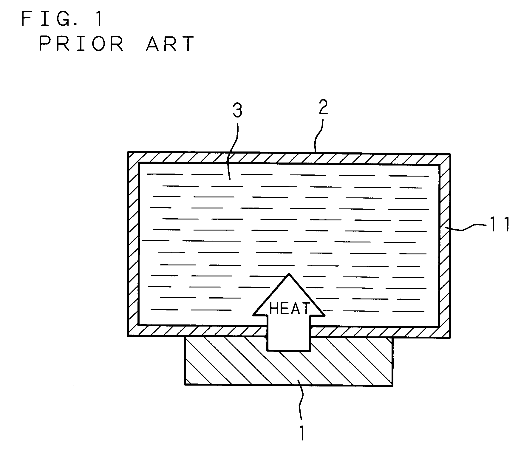
Therefore, the heat from the heat generating member 1 cannot be received efficiently.

Method used


Image

  • Heat receiving member, heat receiving device and electronic equipment
  • Heat receiving member, heat receiving device and electronic equipment
  • Heat receiving member, heat receiving device and electronic equipment

Examples


first embodiment

[0025]FIG. 3 is a sectional view of a heat receiving device 10 according to a first embodiment of the present invention. The coolant passage 2 of the heat receiving member 4 comprises a bag formed of a flexible sheet 11 made up of a thermally stable, flexible plastic material and a metal film having high heat conductivity. In the coolant passage 2 flows a coolant 3 having an anti-corrosion property, such as propylene glycol-based aqueous solution which is a coolant used for a car heat exchanger, for example. The flexible sheet 11 is formed with an opening 11a.

[0026] The heat generating member 1, which is an electronic component, includes a main body 1a and a terminal portion 1b and is supported by an adapter 12 fitted in the opening 11a of the flexible sheet 11. The adapter 12 is provided with a wiring 13 for connecting an electrode of the terminal portion 1b of the heat generating member 1 to an external terminal. The main body 1a of the heat generating member 1 is brought into di...

second embodiment

[0030]FIG. 4 is a sectional view showing a heat receiving device 10 according to a second embodiment of the present invention. The coolant passage 2 comprises a bag made of a flexible sheet 11. In the coolant passage 2 flows a coolant having an anti-corrosion property (e.g. propylene glycol-based aqueous solution). The flexible sheet 11 is formed with an opening 11a, and the heat generating member 1 is fitted in the opening 11a. Part of the flexible sheet 11 is fixed to the sides of the heat generating member 1 by a leak preventing rubber member 14 arranged outside the flexible sheet 11, and the opening 11a is hermetically sealed by the heat generating member 1. Therefore, the coolant 3 does not flow outside the coolant passage 2 through the opening 11a.

[0031] The obverse surface of the main body 1a of the heat generating member 1 comes into direct contact with the anti-corrosion coolant 3 flowing in the coolant passage 2. Therefore, similarly to the first embodiment, the heat resi...


PUM


Abstract

A heat receiving member of a heat receiving device includes a coolant passage comprising a bag formed of a flexible sheet made up of a thermally stable, flexible plastic material and a metal film having high heat conductivity. In the coolant passage flows a coolant having an anti-corrosion property. A heat generating member including a main body and a terminal portion is supported by an adapter fitted in an opening formed in the flexible sheet. The main body of the heat generating member comes into direct contact with the coolant flowing in the coolant passage. Since the heat from the heat generating member is directly transferred to the coolant, the heat transfer path between the heat generating member and the coolant becomes shorter. Therefore, the heat resistance is reduced, so that the heat receiving efficiency is extremely high.

Description

CROSS-REFERENCE TO RELATED APPLICATION [0001] This Nonprovisional application claims priority under 35U.S.C.§119(a) on Patent Application No. 2005-78118 filed in Japan on Mar. 17, 2005, the entire contents of which are hereby incorporated by reference. BACKGROUND OF THE INVENTION [0002] The present invention relates to a heat receiving member for receiving heat from a heat generating member such as an electronic component mounted in an electronic equipment by a coolant flowing in a coolant passage. The invention also relates to a heat receiving device including a heat generating member and a heat receiving member, and an electronic equipment in which a heat generating member is mounted on a printed circuit board. [0003] An electronic equipment such as a desktop computer, a notebook type computer or mobile communication device includes a plurality of electronic components such as a CPU device, a coil element or a capacitor mounted on a printed circuit board. Recently, as the processi...

Claims


Application Information

Patent Timeline
Patent Type & Authority Applications(United States)
IPC IPC(8): H05K7/20F28F7/00
CPCG06F1/203G06F2200/201G06F2200/203
Inventor TANIGUCHI, JUNTOKUHIRA, HIDESHIISHINABE, MINORUASANO, MASATOMONANRI, NOBUHIRO
Owner FUJITSU LTD
Learn More