Method and apparatus for correcting radiographic images

a radiographic image and apparatus technology, applied in the field of radiographic image correcting apparatus, can solve the problems of poor structural noise correction accuracy, unavoidable noise generated by stimulable phosphor sheets, and fixed noise mainly unique noise, and achieve the effect of positively correcting structural nois

a radiographic image and apparatus technology, applied in the field of radiographic image correcting apparatus, can solve the problems of poor structural noise correction accuracy, unavoidable noise generated by stimulable phosphor sheets, and fixed noise mainly unique noise, and achieve the effect of positively correcting structural nois

US20060210135A1Inactive Publication Date: 2006-09-21FUJIFILM CORP +1

Image

  • Method and apparatus for correcting radiographic images
  • Method and apparatus for correcting radiographic images
  • Method and apparatus for correcting radiographic images

Examples


Embodiment Construction

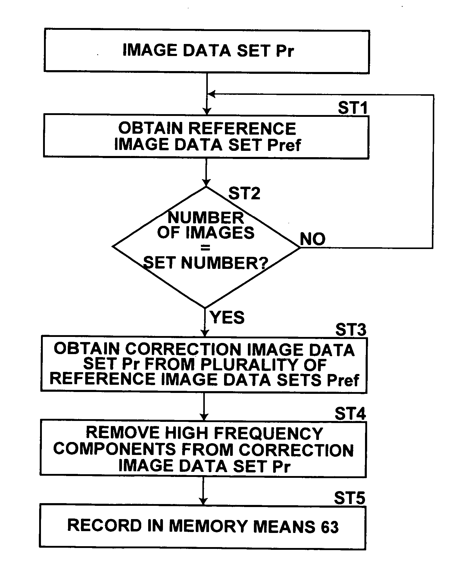
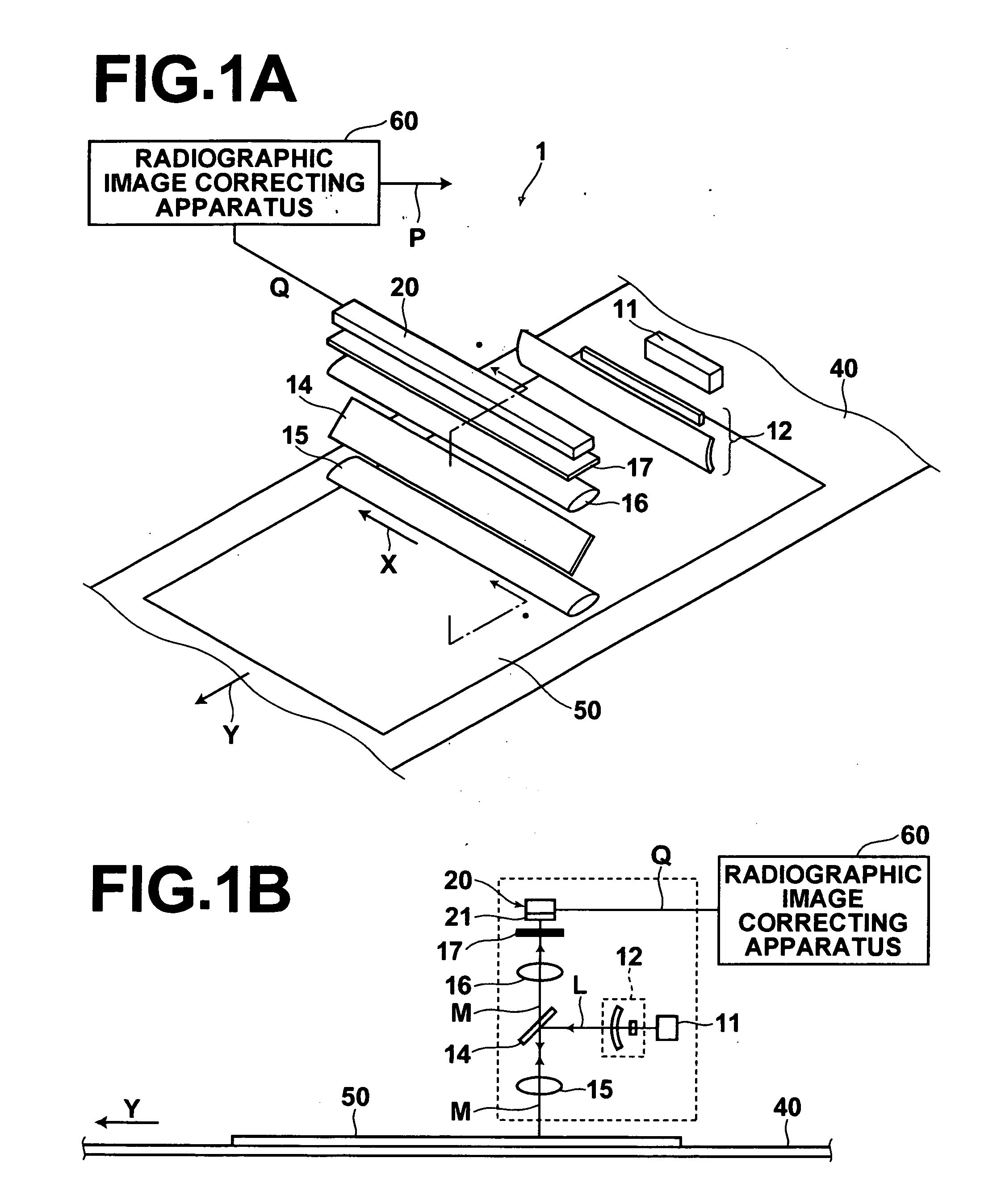
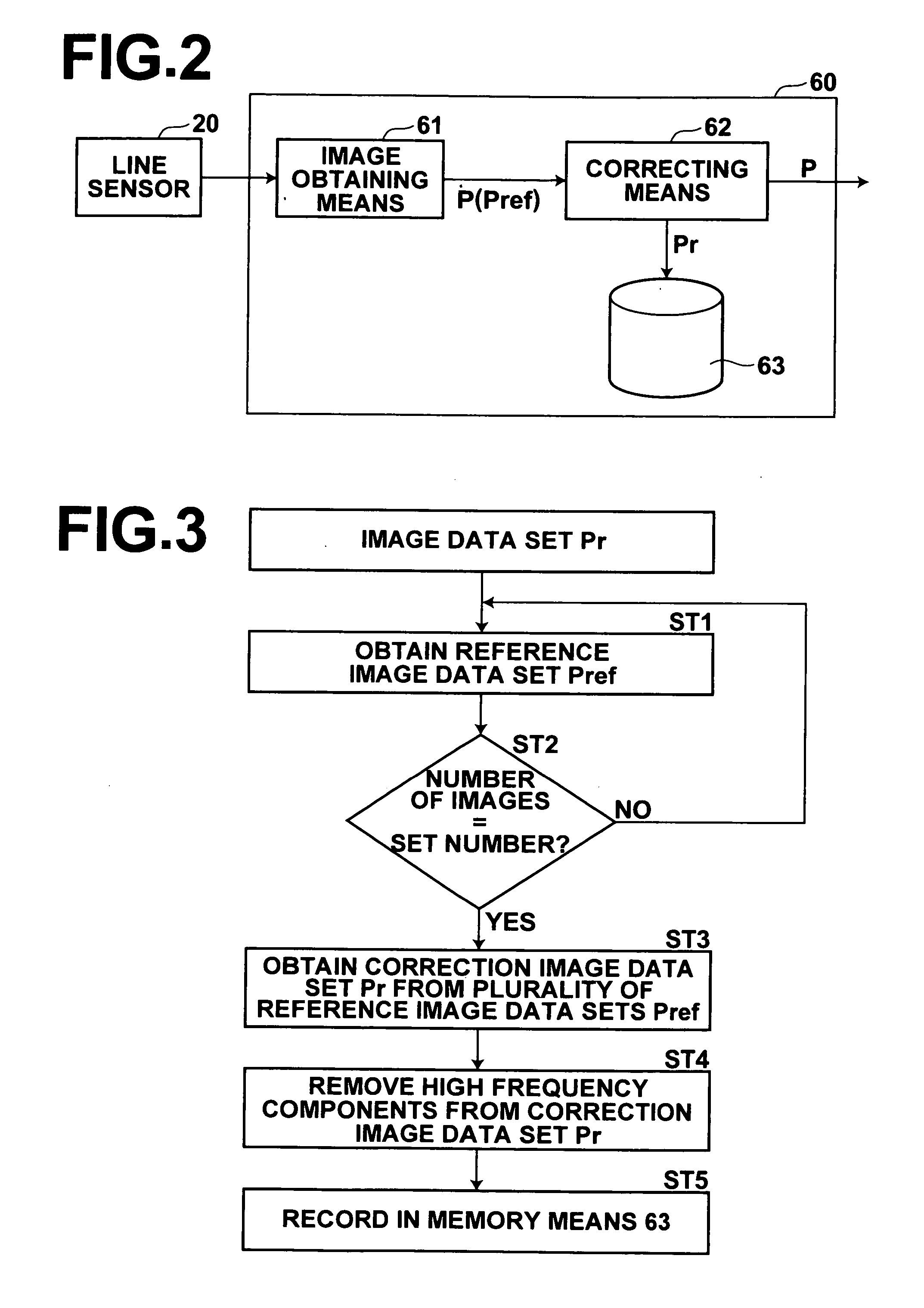
[0030] Hereinafter, an embodiment of the radiographic image correcting apparatus of the present invention will be described in detail with reference to the attached drawings. FIGS. 1A and 1B illustrate an image readout apparatus 1, in which a radiographic image correcting apparatus 60 is incorporated. Note that FIG. 1A is a perspective view of the image readout apparatus, and FIG. 1B is a sectional view taken along line I-I of FIG. 1A.

[0031] The image readout apparatus 1 illustrated in FIGS. 1A and 1B comprises: a scanning belt 40, on which a stimulable phosphor sheet 50 (hereinafter, simply referred to as “sheet 50”) having radiographic image data recorded therein is placed and conveyed in the direction of arrow Y; an excitation light source 11, for emitting a linear secondary excitation light beam L (hereinafter, simply referred to as “excitation light beam”) having a line width of approximately 100 μm onto the surface of the sheet 50 parallel thereto; a line sensor 20 comprising...


PUM


Abstract

Structural noise is accurately removed by a radiographic image correcting apparatus. A correction image data set, generated from a reference image data set obtained from a stimulable phosphor sheet onto which radiation has been uniformly irradiated, that includes at least four times the amount of structural noise compared to quantum noise, is recorded in a memory means. A correcting means corrects a radiographic image data set, employing the correction image data set recorded in the memory means.

Description

BACKGROUND OF THE INVENTION [0001] 1. Field of the Invention [0002] The present invention relates to a radiographic image correcting apparatus, for removing noise from radiographic image data sets, which are obtained from stimulable phosphor sheets. [0003] 2. Description of the Related Art [0004] When certain types of phosphors are irradiated with radiation (X-rays, α-rays, β-rays, γ-rays, electron beams, ultraviolet rays, and the like), a portion of the radiation energy accumulates within the phosphors. When excitation light, such as visible light, is irradiated onto the phosphors, the phosphors emit stimulated phosphorescence corresponding to the energy accumulated therein. Phosphors having this property are referred to as stimulable phosphors. Image readout apparatuses that utilize these stimulable phosphors have been proposed. Radiographic image information of a subject, such as a human body, is temporarily recorded in a stimulable phosphor sheet. Then, excitation light is irrad...

Claims


Application Information

Patent Timeline
21 Sep 2006
Publication
US20060210135A1
IPC
G06K9/00; G06K9/40
CPC
G06T2207/10116; G06T5/002; G06T5/50; A61B6/4494; G06T5/70
Inventors
KANEGAE, YUKIO