Power tool gear-train and torque overload clutch therefor

a technology of torque overload clutch and gear train, which is applied in the direction of manufacturing tools, portable power-driven tools, and gearing, and achieves the effect of convenient us

Active Publication Date: 2006-09-21
BLACK & DECKER INC
View PDF19 Cites 30 Cited by
  • Summary
  • Abstract
  • Description
  • Claims
  • Application Information

AI Technical Summary

Benefits of technology

[0017] Preferably, the dial comprises a collar wrapped around the gearbox next to the motor housing, between the motor housing and gearbox, or on or around the motor housing. Preferably, the collar is flush with the outer surface of gearbox and / or motor housing. This provides a relatively compact arrangement, which is also easy to use and aesthetically pleasing.

Problems solved by technology

Furthermore, this arrangement leaves space free on the front end of the power tool closest to the chuck in which ancillary devices, such as work-piece illuminators can be disposed.

Method used


Image

  • Power tool gear-train and torque overload clutch therefor
  • Power tool gear-train and torque overload clutch therefor
  • Power tool gear-train and torque overload clutch therefor

Examples


first embodiment

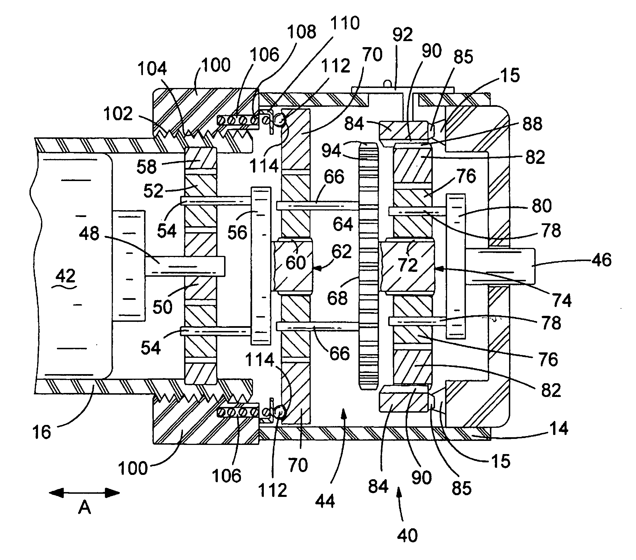
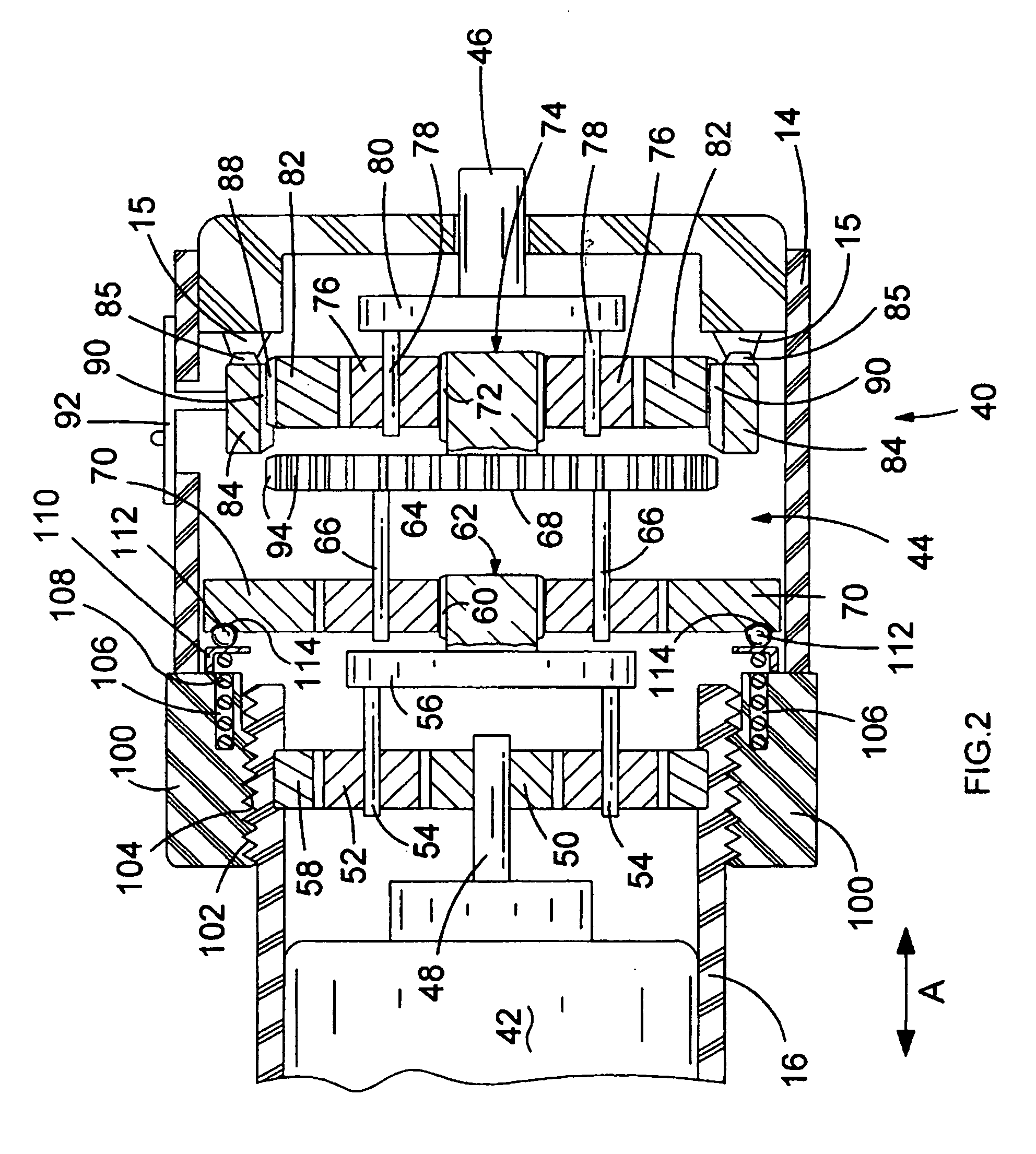
[0026] Referring to FIG. 2, a screwdriver's drive train 40 is shown in highly schematic cross-sectional form. An electric motor 42 is disposed in a motor housing 16, and a gear train 44 is disposed in a gearbox 14. The motor has an output drive spindle 48 which rotates when the motor is activated. The gear train's output 46 is in communication with the screwdriver's collet (not shown).

[0027] A first gear 50 is rigidly mounted on to the motor's spindle 48, and thus rotates when the motor is activated. The first gear 50 is the so-called sun-gear. Three planet gears 52 (there are only two gears shown in FIG. 2 for clarity reasons) are rotatably mounted on spindles 54 of a first stage carrier 56 and are arranged to mesh with the first gear 50. A planet ring gear 58 is rigidly mounted to the motor housing 16 and the planet gears 52 mesh with the planet ring gear. Thus, rotation of the first gear 50 causes rotation of the planet gears 52, and because the planet ring 58 is mounted rigidly ...

second embodiment

[0049] The embodiments described provide a compact power tool transmission. This is achieved by arranging the clutch mechanism around the gear train, around a portion of the motor, and / or in a space between the motor and gear train. By comparison, a conventional clutch mechanism is arranged with at least a portion of the clutch being disposed around the gear train's output spindle. Thus, embodiments of the present invention can provide a power tool of considerably shorter length compared to conventional units. Furthermore, some components of the clutch described in the second embodiment utilises a space or volume defined by a part of the motor, the gear train, and either the motor housing and / or gearbox. Thus, further compactness is achieved compared to conventional power tool clutch mechanisms. Disposing the clutch mechanism's adjustment collar towards the rear of the gear train leaves a space unutilised at the front end of the power tool. This unutilised space can be used to provi...


PUM


Abstract

A power tool transmission is described in which an overload clutch mechanism is arranged to provide a relatively compact power tool. A torque adjustment dial is arranged between the visible portions of the motor housing and the gearbox, and the dial is coupled to a compression spring such that rotation of the dial cause the spring to be compressed or decompressed, thereby adjusting the torque at which the clutch overloads and ratchets. The compression spring is arranged at least partially between the motor and gearbox or gear train, in a space which conventional power tools do not utilised for this purpose. Thus, the dimensions of the power tool's transmission can be reduced with respect to conventional power tools. Furthermore, the space on the gearbox immediately behind a chuck can be used for another purpose other than accommodating the adjustment collar, as is the case with conventional power tools.

Description

FIELD OF THE INVENTION [0001] This invention relates to a power tool having a gear train and torque overload clutch. In particular, this invention relates to hand-held motor driven electric power tool, but it might equally be applicable to other forms of power tools. BACKGROUND OF THE INVENTION [0002] It is known for hand-held motor driven power tools, particularly screwdrivers, to incorporate a clutch overload mechanism, usually in the gearbox. The clutch is arranged to interrupt or break the drive train when a torque force applied to the power tool's output exceeds a threshold value. This can be achieved by causing components of the gear train to slip or ratchet with respect to one another. In this instance the motor continues to operate but the gearbox output, and hence the tool bit, does not rotate. Thus, the clutch can be used to prevent a nut or screw from being tightened beyond a certain torque (at which the thread might be stripped, for instance). [0003] The gear train in co...

Claims


Application Information

Patent Timeline
Patent Type & Authority Applications(United States)
IPC IPC(8): F16H3/44B25B23/14
CPCB25B21/00B25B23/141B25F5/001
Inventor ROBERTS, ANA-MARIAPROUDLOCK, DAVID
Owner BLACK & DECKER INC
Why Eureka
Try Eureka