Surgical suture cutter

Inactive Publication Date: 2006-09-21
TELEFLEX MEDICAL INC
View PDF6 Cites 70 Cited by
  • Summary
  • Abstract
  • Description
  • Claims
  • Application Information

AI Technical Summary

Benefits of technology

[0007] The foregoing needs are met, to a great extent, by the present invention, wherein in one aspect an apparatus is provided that in some embodiments provides a surgical suture cutting instrument that provides an enhanced accuracy of cutting, an enhanced stability and ease of cutting, and provides for interchan

Problems solved by technology

However, many of the prior art cutters suffer from imprecise cutting elements, resulting in cutting actions that can be unstable or difficult to perform during surgery.
Further

Method used


Image

  • Surgical suture cutter
  • Surgical suture cutter
  • Surgical suture cutter

Examples


Example

[0031] In accordance with conventional practice, as used herein, the term “proximal” or “proximal end” shall refer to the specified end of a device or its component which is generally closer to the medical personnel handling or manipulating the device as it is intended to be used, and the term “distal” or “distal end” shall refer to the specified end of a device or its component which is opposite the proximal end.

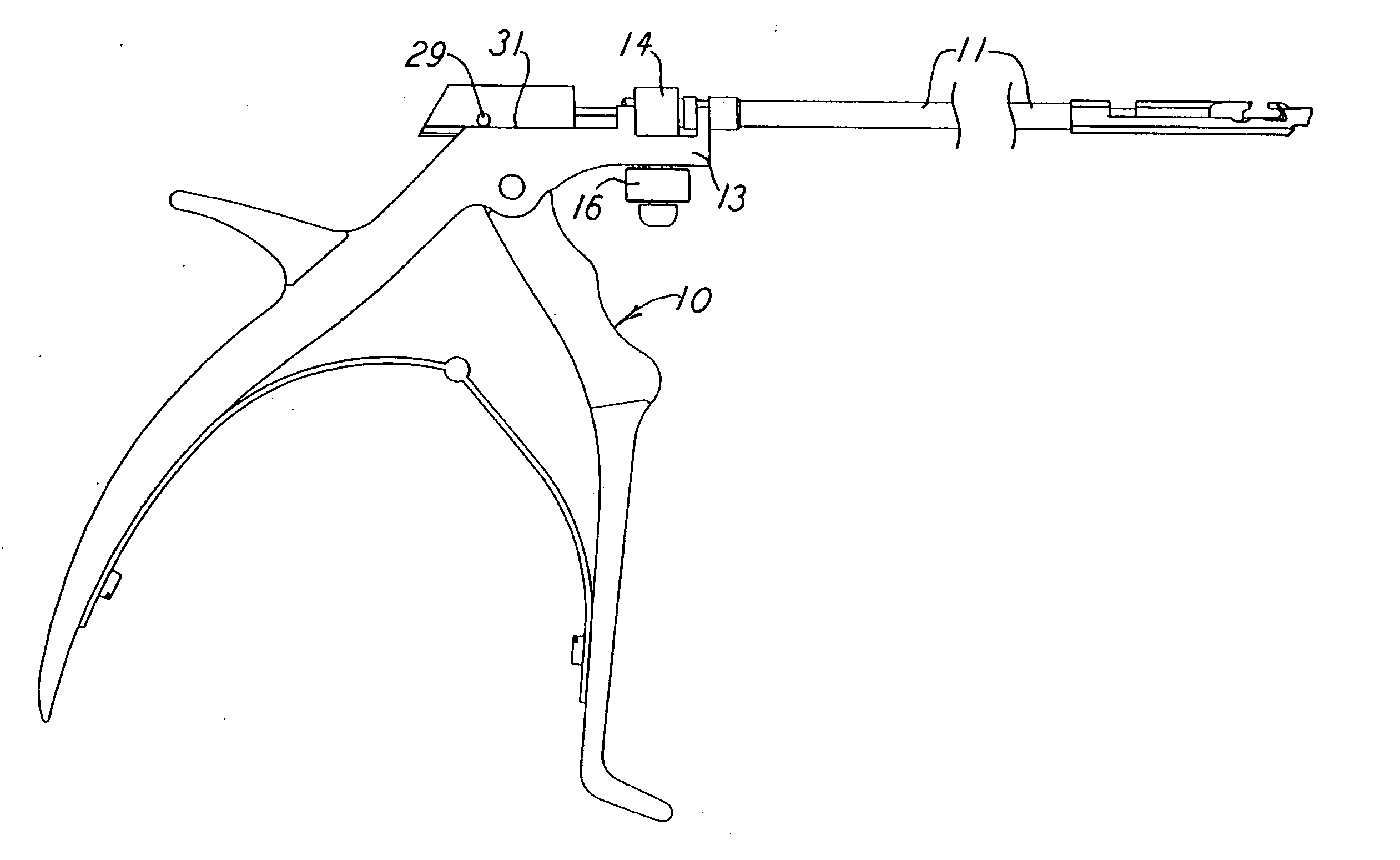
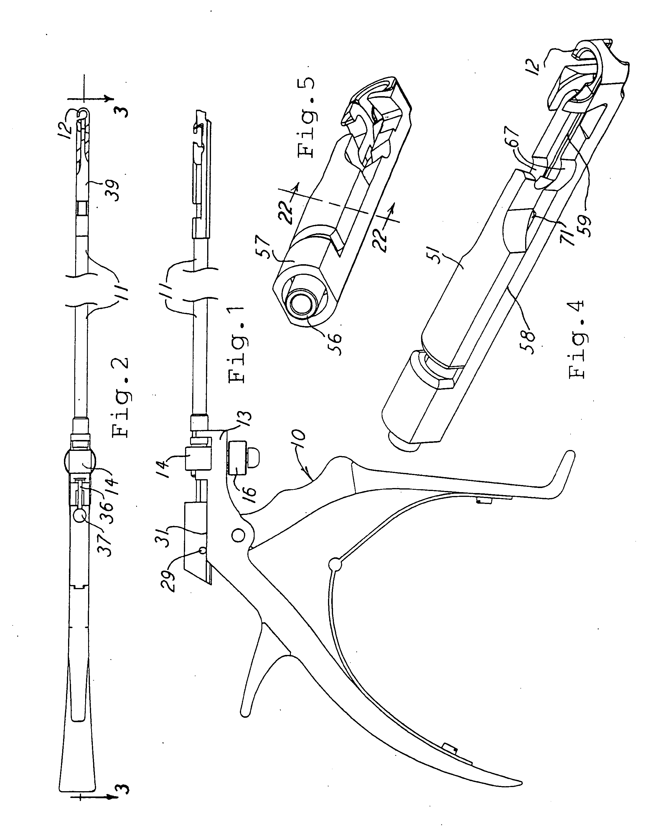
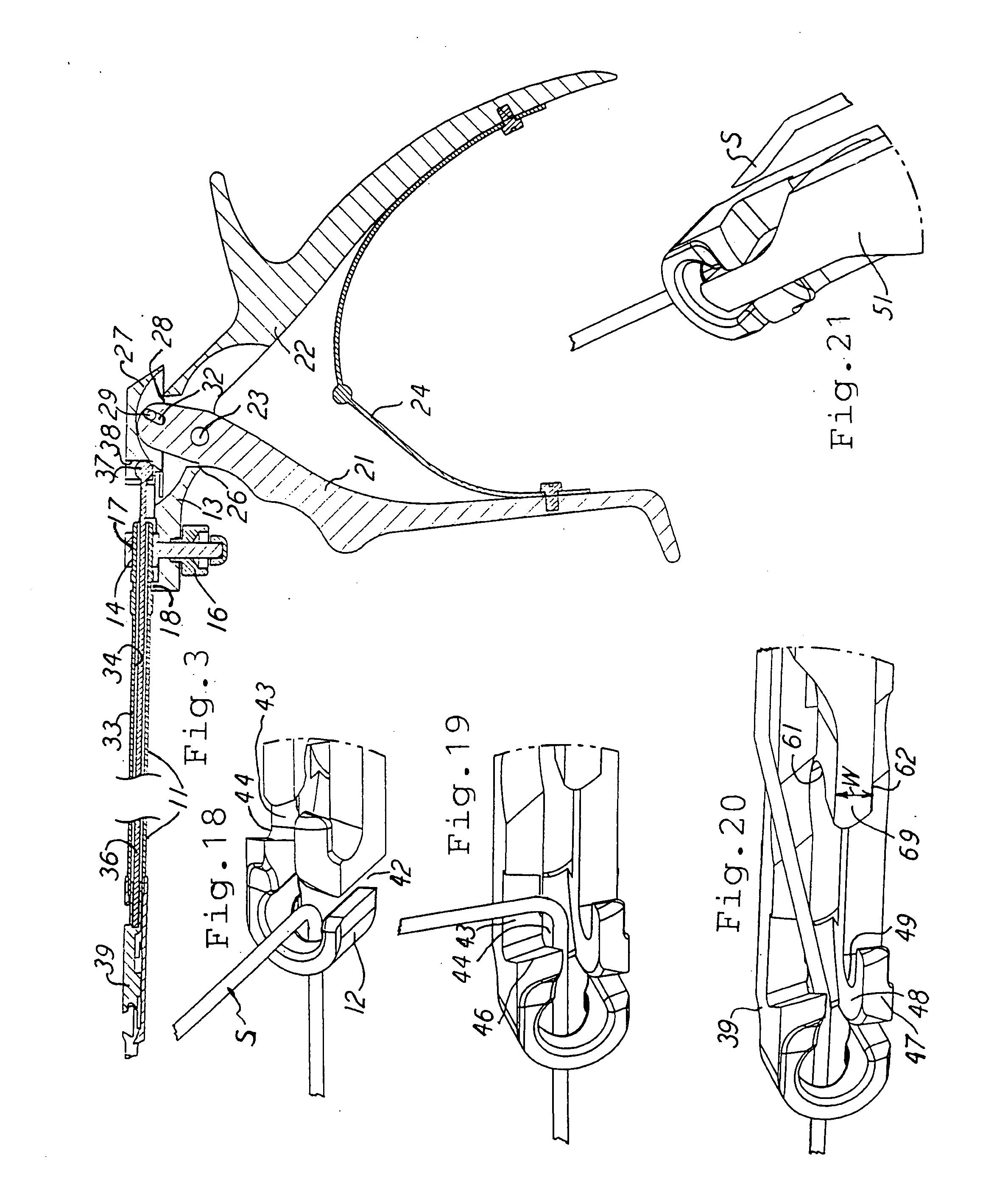
[0032] Generally the drawings show a suture cutter having a handle portion 10 and a barrel portion 11. The distal end of the barrel has a hook 12 which snares the suture to be cut, and the hook can then be slid along the suture to a selected length location for making the actual cut as desired. The handle includes a support portion 13 which has a bolt 14 passing therethrough, and a nut 16 secures the bolt to the handle. The bolt 14 has a passageway 17 therethrough, and the barrel 11 is nested therein for secure mounting of the barrel. Also, the barrel 11 and the handle por...


PUM


Abstract

A suture cutter having a handle and a barrel with a movable cutting head on the barrel, and the barrel supporting a stationary cutting edge and a movable cutting edge. A movable support carries the movable cutting edge and includes a surface spaced from the stationary cutting edge a selected distance. An abutment wall spaced from the stationary cutting edge at the selected distance provides for snugly restricting movement of the moving cutting edge away from cutting contact with the stationary cutting edge while cutting the suture. Recesses are defined on a guiding support surface along which the movable cutting edge slides when the handle is actuated, allowing for sharpening of the moveable cutting edge when said edge is retracted proximally.

Description

CROSS-REFERENCE TO RELATED APPLICATIONS [0001] This application claims priority from U.S. provisional patent application No. 60 / 659,457, filed Mar. 8, 2005, the disclosure of which is hereby incorporated by reference in its entirety.FIELD OF THE INVENTION [0002] This relates to medical devices, and, more particularly, to a surgical suture cutter which has a handle portion and a barrel portion. BACKGROUND OF THE INVENTION [0003] The prior art is already aware of cutters with squeezable handles which support a cutter blade for operating the cutter blade in cutting operation of a line to be cut. Those cutters also have provision for interchanging the cutting portion with respect to the supporting handle for selection of particular cutters to be applied to the line to be cut. However, many of the prior art cutters suffer from imprecise cutting elements, resulting in cutting actions that can be unstable or difficult to perform during surgery. Furthermore, the cutters are difficult to cle...

Claims


Application Information

Patent Timeline
IPC IPC(8): A61B17/10
CPCA61B17/0467A61B17/320016A61B17/3201A61B2017/0046A61B2017/2944
Inventor SCHILLING, PETERHIPP, LOTHAR U.RINNER, JAMES A.DARUWALA, DARIUS P.
Owner TELEFLEX MEDICAL INC
Why Eureka
Try Eureka