
Esophageal stent

a technology of esophageal stent and esophageal artery, which is applied in the field of esophageal stent, can solve the problems of pain in patients, difficulty in ensuring the operation of the patient, so as to maximize the operational reliability of the esophageal stent and prevent the reverse flow of gastric contents

Active Publication Date: 2006-09-21
TAEWOONG MEDICAL CO LTD
View PDF6 Cites 31 Cited by
  • Summary
  • Abstract
  • Description
  • Claims
  • Application Information

AI Technical Summary

Benefits of technology

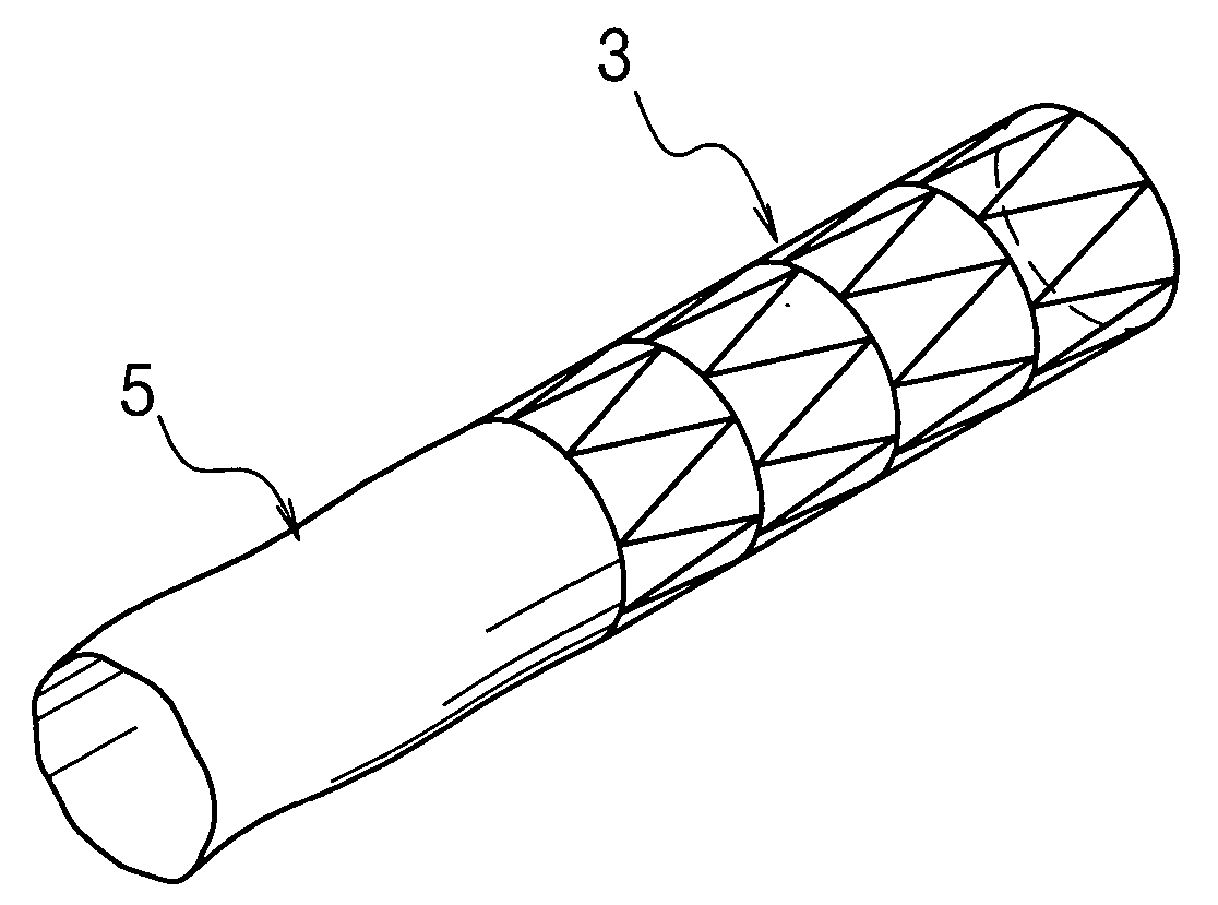
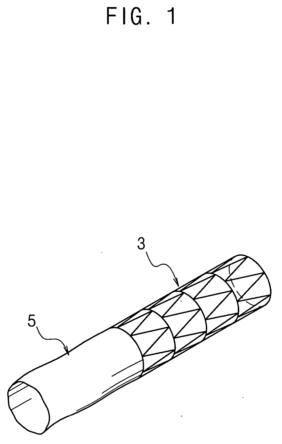
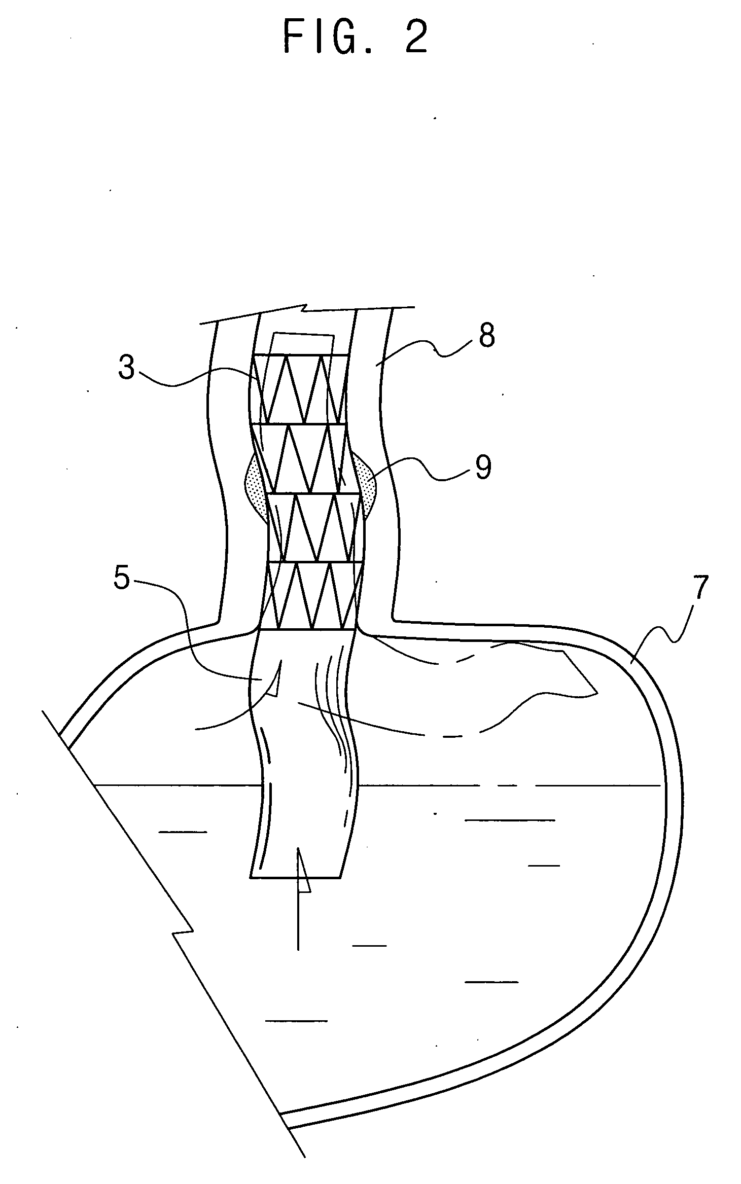
The present invention provides an esophageal stent with a flexible tube that prevents the reverse flow of gastric contents and maximizes the operational reliability of the stent. The flexible tube is designed to prevent inversion and does not cause patient pain or discomfort due to frictional contact with the stomach. The stent comprises a stent body with a hollow cylindrical mesh structure fabricated by weaving superelastic shape-memory alloy wires, and the flexible reverse flow prevention tube is coupled to the lower end of the stent body. The flexible reverse flow prevention tube has an inside membrane and an outside membrane adhered to each other, with a core longitudinally placed between the membranes. The core extends from the upper end of the flexible tube a distance of at least half of its length.

Problems solved by technology

However, surgery to the stenosed gullet causes pain to the patient and, furthermore, surgery is not as effective as desired.
However, the conventional reverse flow prevention tube 5 provided on the esophageal stent is problematic as follows.
Thus, the patient feels pain.
However, the stent has the same problem experienced with conventional esophageal stents.

Method used


Image

  • Esophageal stent
  • Esophageal stent
  • Esophageal stent

Examples


third embodiment

[0043] The flexible reverse flow prevention tube 15 having the core 20 or 20′ according to the present invention may be used with an esophageal stent body 13 having a simple cylindrical shape, as shown in FIGS. 3, 4 and 5. However, it should be understood that the flexible tube 15 having the core 20 or 20′ may be used with an esophageal stent body 13 according to the present invention, in which an enlarged diameter part 13a is provided on each end of the stent body 13 so that the stent body 13 can be caught and reliably maintained in a designated part of the gullet, as shown in FIG. 6.

fourth embodiment

[0044] Furthermore, the flexible reverse flow prevention tube 15 having the core 20 or 20′ may be used with another type of esophageal stent body having a coating layer or an artificial membrane to prevent food from coming into contact with a lesioned part of the gullet and from causing pain to a patient while the food flows through the gullet, according to the present invention.

[0045] The esophageal stent, including a stent body 13 having an artificial membrane 40 and a flexible reverse flow prevention tube 15′ according to the fourth embodiment of the present invention, is configured as follows. As shown in FIGS. 7 and 8, the esophageal stent comprises an inside stent body 13′ and an outside stent body 13″, each having a hollow cylindrical mesh structure fabricated by weaving superelastic shape-memory alloy wires, with an artificial membrane 40 placed between the inside and outside stent bodies 13′ and 13″.

[0046] The esophageal stent of the fourth embodiment further comprises a r...


PUM


Abstract

Disclosed is an esophageal stent placed in a stenosed part of the esophagus having a flexible tube to prevent the reverse flow of gastric contents from the stomach is coupled to the lower end of the esophageal stent. The flexible tube has an inside membrane and an outside membrane adhered to each other, thus having a twofold structure with at least one core longitudinally placed between the adhered inside and outside membranes while the core extends from the upper end toward the lower end of the flexible tube. Thus, the flexible tube is prevented from being inverted, and prevents the reverse flow of the gastric contents, and maximizes the operational reliability of the esophageal stent. The flexible tube does not cause a patient pain or discomfort due to frictional contact of the tube with the inner surface of the stomach when the tube moves in the stomach.

Description

BACKGROUND OF THE INVENTION [0001] The present invention relates generally to an esophageal stent to be placed in a stenosed part of the esophagus or gullet, which communicates with the stomach, thus enlarging the size of the passage of the stenosed part and making swallowing easier and, more particularly, to an esophageal stent which has a flexible tube coupled to the lower end of the esophageal stent such that the flexible tube is placed in the stomach and prevents reverse flow of gastric contents from the stomach, with an elastic core being set in the flexible tube and preventing inversion of the tube, thus efficiently preventing the gastric contents from reversely flowing from the stomach. [0002] The esophagus, or gullet, may be narrowed and, furthermore, blocked by stenosis caused by cancer, and, in the related art, such stenosed part of the gullet may be treated by surgery. However, surgery to the stenosed gullet causes pain to the patient and, furthermore, surgery is not as e...

Claims


Application Information

Patent Timeline
Patent Type & Authority Applications(United States)
IPC IPC(8): A61B17/08A61F2/82A61M29/02
CPCA61F2/24A61F2/82A61F2/90A61F2002/044A61F2/04A61F2/2418A61F2/91A61F2210/0014
Inventor SHINKIM, JIN-HONGYOSHINORI, MIZUMOTO
Owner TAEWOONG MEDICAL CO LTD
Learn More