Control apparatus for internal combustion engine and control method for the same

a control apparatus and internal combustion engine technology, applied in mechanical apparatus, electric control, machines/engines, etc., can solve the problems of excessive increase of charging pressure, insufficient enhancement of fuel efficiency in supercharging operation using turbocharger, etc., and achieve the effect of reducing pumping loss

Inactive Publication Date: 2006-09-28
DENSO CORP
View PDF27 Cites 43 Cited by
  • Summary
  • Abstract
  • Description
  • Claims
  • Application Information

AI Technical Summary

Benefits of technology

[0008] In view of the foregoing and other problems, it is an object of the present invention to produce a control apparatus for an internal combustion engine having a turbocharger, the control apparatus being capable of controlling charging pressure and enhancing fuel efficiency. It is another object of the present invention to produce a control method for the internal combustion engine.
[0011] Thus, the position of the waste gate valve is electrically controlled, regardless of the charging pressure, so that exhaust pressure decreases, thereby reducing a pumping loss.

Problems solved by technology

However, in this conventional structure, in general, when charging pressure increases, the WGV 88 is opened, so that charging pressure is restricted from excessively increasing.
Accordingly, fuel efficiency cannot be sufficiently enhanced in a supercharging operation using a turbocharger.

Method used


Image

  • Control apparatus for internal combustion engine and control method for the same
  • Control apparatus for internal combustion engine and control method for the same
  • Control apparatus for internal combustion engine and control method for the same

Examples


embodiment

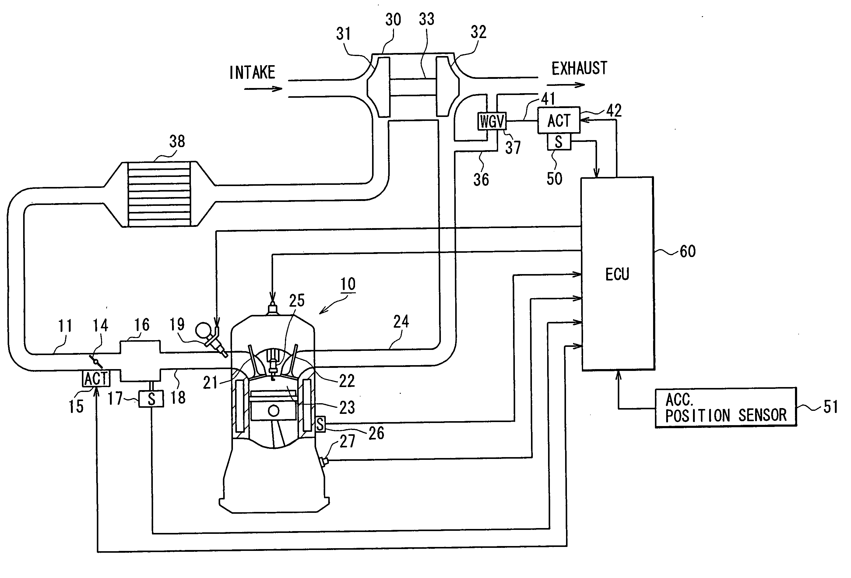
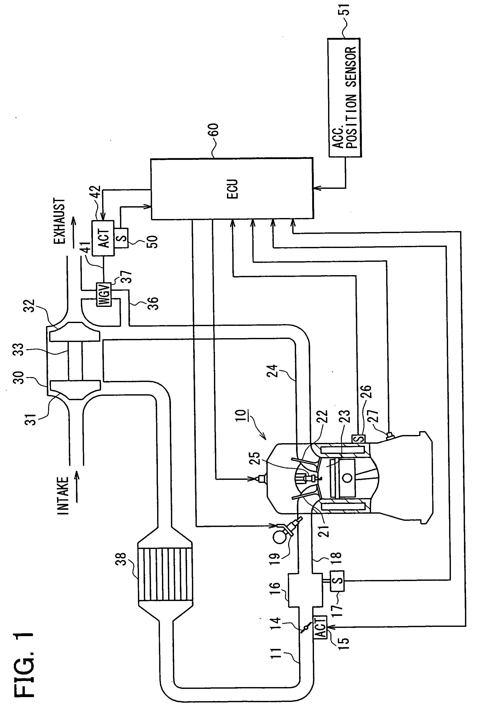
[0023] An internal combustion engine 10 shown in FIG. 1 has multiple cylinders. This multi cylinder engine 10 has an intake pipe (intake passage) 11 that accommodates a throttle valve 14 controlled using a throttle actuator 15 such as a DC motor. The throttle valve 14 serves as an intake amount control unit. The throttle actuator 15 has a throttle position sensor that detects an opening angle (throttle position) of the throttle valve 14. A surge tank 16 is provided to the downstream of the throttle valve 14. The surge tank 16 is provided with an intake pressure sensor 17 that detects intake pressure downstream of the throttle valve 14. The surge tank 16 is connected with an intake manifold 18, through which intake air is distributed into respective cylinders of the engine 10. Fuel injection valves 19 are provided to the intake manifold 18. Each of the fuel injection valves 19 is arranged in the vicinity of each intake port of each cylinder. The fuel injection valve 19 has an actuato...


PUM


Abstract

An engine includes a throttle valve provided to an intake passage and a turbocharger, which includes an exhaust turbine and an intake compressor. The intake compressor is arranged in the intake passage. A waste gate valve operated using an electric actuator is provided to a bypass passage, which bypasses the exhaust turbine. A control apparatus for the engine includes a setting unit and a control unit. The setting unit sets the position of the waste gate valve at a target position in a normal operating condition of the engine. The target position is out of a position range, in which the waste gate valve is in a substantially full close position. The control unit controls the position of the waste gate valve such that the position of the waste gate valve coincides with the target position.

Description

CROSS REFERENCE TO RELATED APPLICATIONS [0001] This application is based on and incorporates herein by reference Japanese Patent Application No. 2005-91308 filed on Mar. 28, 2005. FIELD OF THE INVENTION [0002] The present invention relates to a control apparatus for an internal combustion engine having a turbocharger, and relates to a control method for the internal combustion engine. BACKGROUND OF THE INVENTION [0003] Conventionally, a charging device such as a turbocharger is applied to an internal combustion engine for enhancing efficiency of intake air, thereby increasing engine power. According to JP-A-7-332097, a charging control apparatus is provided to an engine for controlling a charging device. A bypass passage is provided to bypass an exhaust turbine provided to an exhaust pipe. A waste gate valve is provided to the bypass passage for controlling an amount of exhaust gas flowing into an exhaust turbine, thereby controlling charging pressure. [0004] In general, a waste gat...

Claims


Application Information

Patent Timeline
Patent Type & Authority Applications(United States)
IPC IPC(8): F02D23/00F02B33/44
CPCF01N3/00F02B29/0406F02D11/105F02D23/00F02D41/0007F02D2250/18Y02T10/144Y02T10/20Y02T10/12F02B37/12F02B37/18
Inventor HASEGAWA, JUN
Owner DENSO CORP
Why Eureka
Try Eureka