
Panel bending machine

a technology of bending machine and panel, which is applied in the direction of material strength using steady bending force, instruments, and material analysis, etc., can solve the problem of a slight increase in the slope of the line used to calculate stiffness

Active Publication Date: 2006-09-28
HUBER ENGINEERED WOODS
View PDF22 Cites 23 Cited by
  • Summary
  • Abstract
  • Description
  • Claims
  • Application Information

AI Technical Summary

Benefits of technology

[0007] The above needs are met and other advantages and benefits are achieved by the present invention in which a panel testing device for flexing and measuring mechanical properties of a panel is provided comprising a panel bending assembly operable to engage a panel and impart a bending force on the engaged panel, and includes a linear actuator having an output shaft coupled to the panel bending assembly where movement of the output shaft correspondingly changes the bending force applied to a test panel engaged by the panel bending assembly, and wherein the output shaft is operable to be movable relative to the panel bending assembly continuously at a constant rate of linear motion regardless of the torque force resisting such motion at the panel testing assembly. A position feedback assembly is included operable to generate signals corresponding to the position and velocity of the output shaft of the linear actuator, and a deflection measurement assembly included is operable to measure a deflection of the panel during a testing cycle. A control system also included which is operable to communicate with the linear actuator, position feedback assembly, and the deflection measurement assembly for controlled operation thereof, including receiving first signals from the deflection measurement assembly that correspond to the deflection of the panel and second signals from the position feedback assembly that correspond...

Problems solved by technology

Unlike some prior systems, the output shaft of the linear actuator delivers a continuous actuation stroke during and throughout a given panel test cycle without pausing or hesitating, especially during the beginning of a test cycle where such undesired phenomenon has been observed to be more prone to occur in prior systems.
In this instance, the decrease in variation results in a slight increase in the slope of the line used to calculate stiffness of the panel being tested.

Method used


Image

  • Panel bending machine
  • Panel bending machine
  • Panel bending machine

Examples


Embodiment Construction

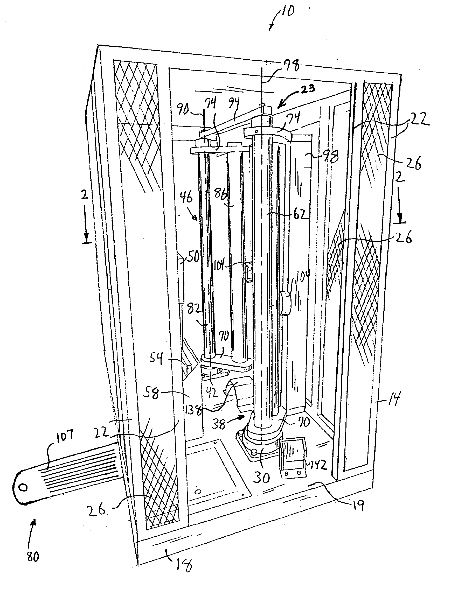
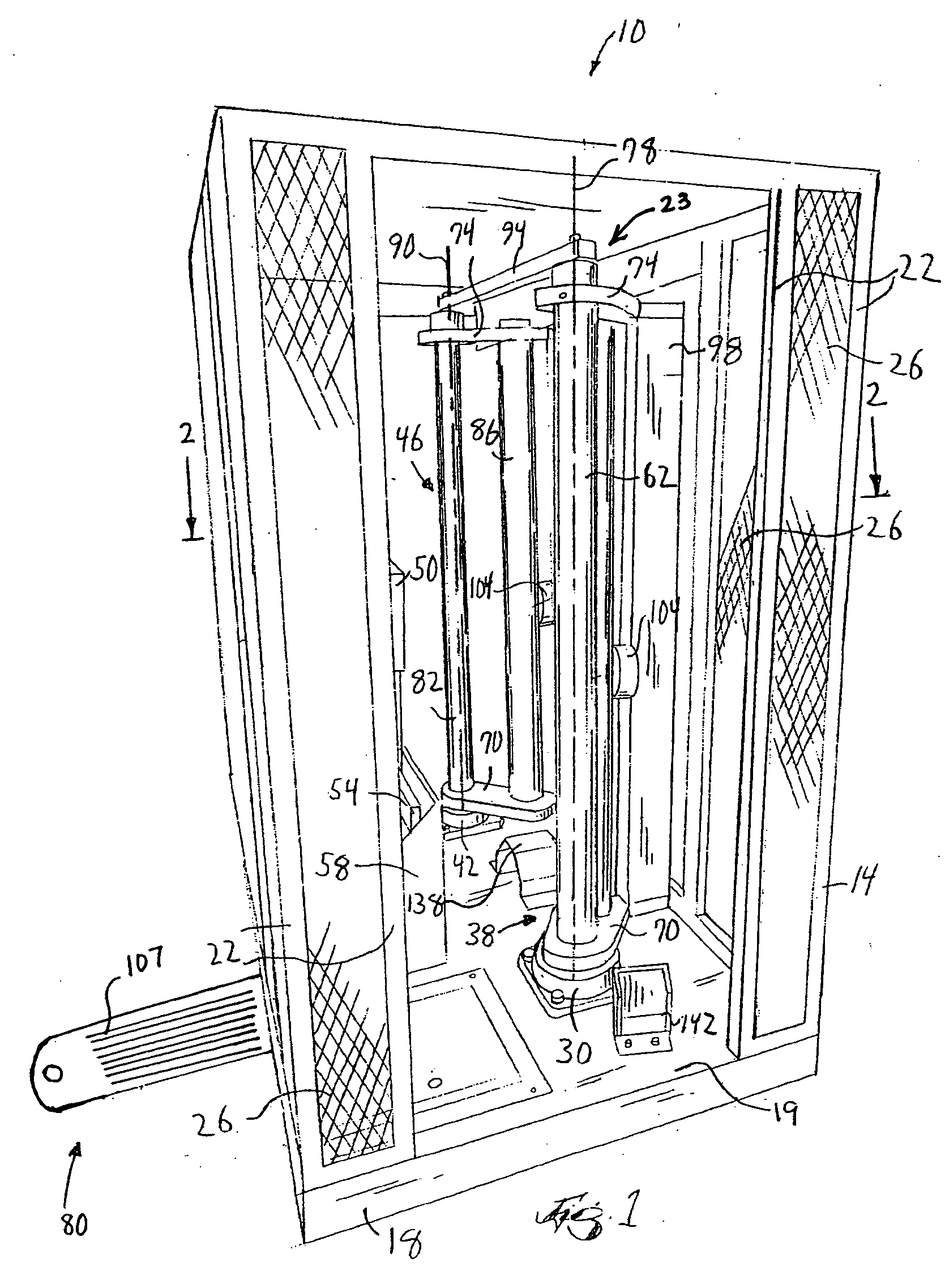
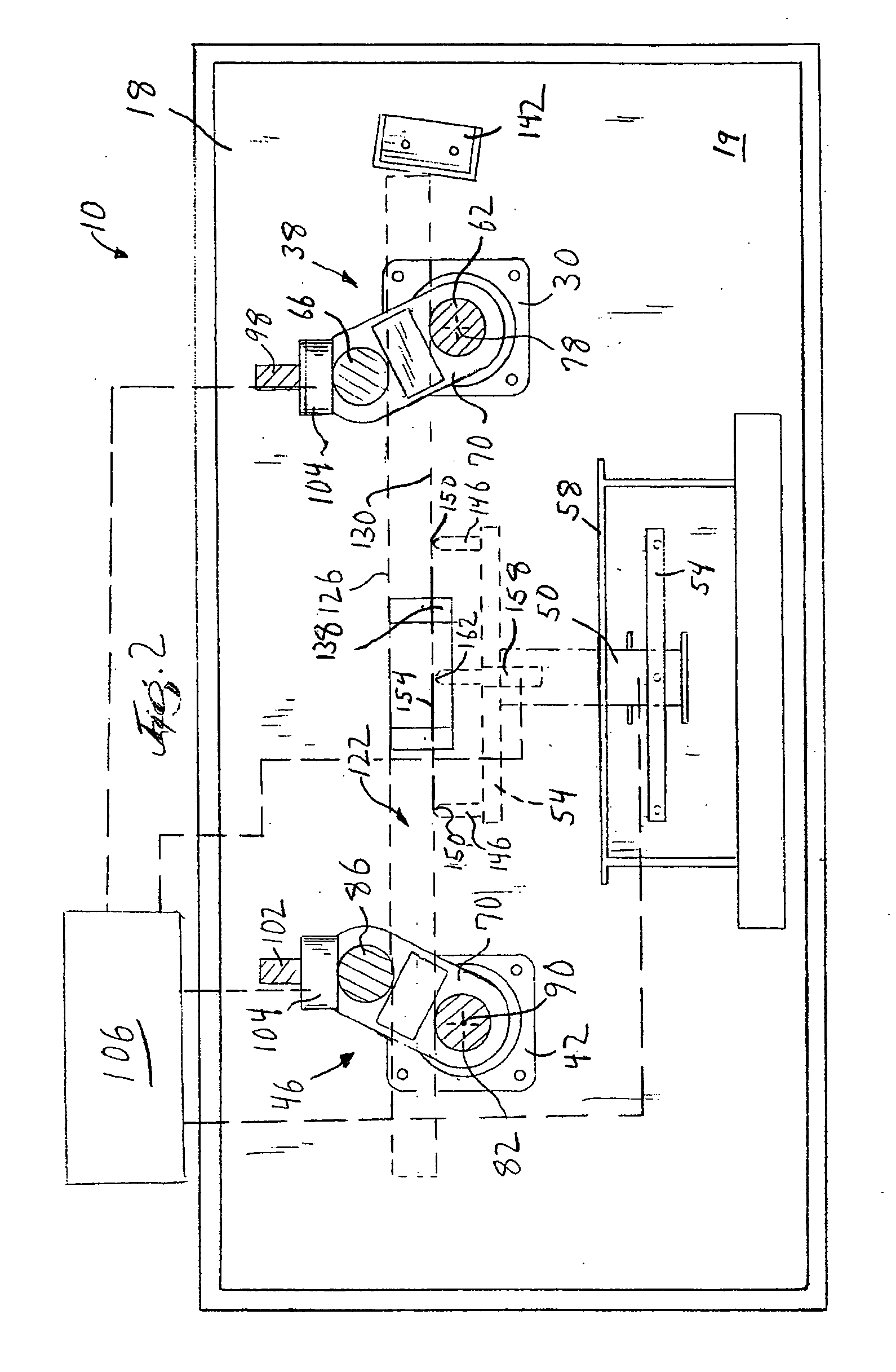
[0027] Preferred embodiments of the invention are described below by referring to the drawings. Referring to FIG. 1, a panel testing device 100 is shown which includes of a metal cage (frame) 14 with two sets of two arm assemblies 38, 46 that rotate and flex a panel to determine mechanical properties of the panel, such as find deflection between two loads (stiffness) and failure at ultimate load (strength).

[0028] When determining mechanical properties of test panels according to standard methods of testing in flexure, such as in accordance with ASTM D 3043-95, method C, in which load deflection curves can be measured and used to determine bending stiffness, etc., it is important to provide and maintain a continuous constant load applied as equal and opposite pure moments to each end of the test panel throughout the test cycle. However, test panels may generate a variable amount of counter-torque force against the bending force applied to it by the panel testing machine during a giv...


PUM


Abstract

A panel testing device, and a method of its use, for flexing and measuring mechanical properties of a panel are provided comprising a panel bending assembly operable to engage a panel and impart a bending force on the engaged panel, and a linear actuator having an output shaft coupled to the panel bending assembly, wherein the output shaft is operable to be movable relative to the panel bending assembly continuously at a constant rate of linear motion regardless of the torque force resisting such motion at the panel testing assembly.

Description

FIELD OF THE INVENTION [0001] This invention relates to devices for testing mechanical properties of panel materials, and methods of use thereof. BACKGROUND OF THE INVENTION [0002] An increasing demand exists for pre-fabricated structural panel materials, such as plywood, wafer board, oriented strand board, plaster board, composites of veneer and of wood-based layers, and so forth. These structural materials are heavily used, for instance, in the construction and manufacturing industries. Suppliers and users of these products often need to know their flexural properties, e.g., elastic and strength properties, to assist them in making a proper material selection. Specimen or control panels cut from large panels or pulled from a given production lot are tested to determine the flexural properties of the panel material. It is imperative that the testing arrangement used for these tests yields accurate, reliable and repeatable results to increase confidence that the control panel result...

Claims


Application Information

Patent Timeline
IPC IPC(8): G01N3/20
CPCG01N3/20G01N33/46G01N2203/0282
Inventor DOAK, JODYGUFFEY, SHANNON D.
Owner HUBER ENGINEERED WOODS
Learn More