Printing and drying method, method of production of electronic device, and printing and drying system

Active Publication Date: 2006-09-28
TDK CORPARATION
View PDF6 Cites 11 Cited by
  • Summary
  • Abstract
  • Description
  • Claims
  • Application Information

AI Technical Summary

Benefits of technology

[0036] Preferably, the takeup zone is provided with a destaticizer which removes static electricity of the support sheet passing through the takeup zone. By removing the static electricity, the support sheet can be prevented from deposition of dust etc. and defects due to the deposition of dust or other foreign matter can be prevented.
[0037] Preferably, the third tension per unit width of the support sheet is 0.5 to 0.8 N/cm along the support she

Problems solved by technology

Due to this, sheet delamination, stack deformation, etc. become problems.
The heat at the time of drying probably ends up causing shrinking along the long direction.
In particular, due to the patterns of the electrode layer 12a being made finer and thinner, the positional deviation at the time of printing causes sheet delamination,

Method used


Image

  • Printing and drying method, method of production of electronic device, and printing and drying system
  • Printing and drying method, method of production of electronic device, and printing and drying system
  • Printing and drying method, method of production of electronic device, and printing and drying system

Examples


first embodiment

[0049] Overall Configuration of Multilayer Ceramic Capacitor

[0050] First, as a first embodiment of an electronic device according to the present invention, the overall configuration of a multilayer ceramic capacitor will be explained.

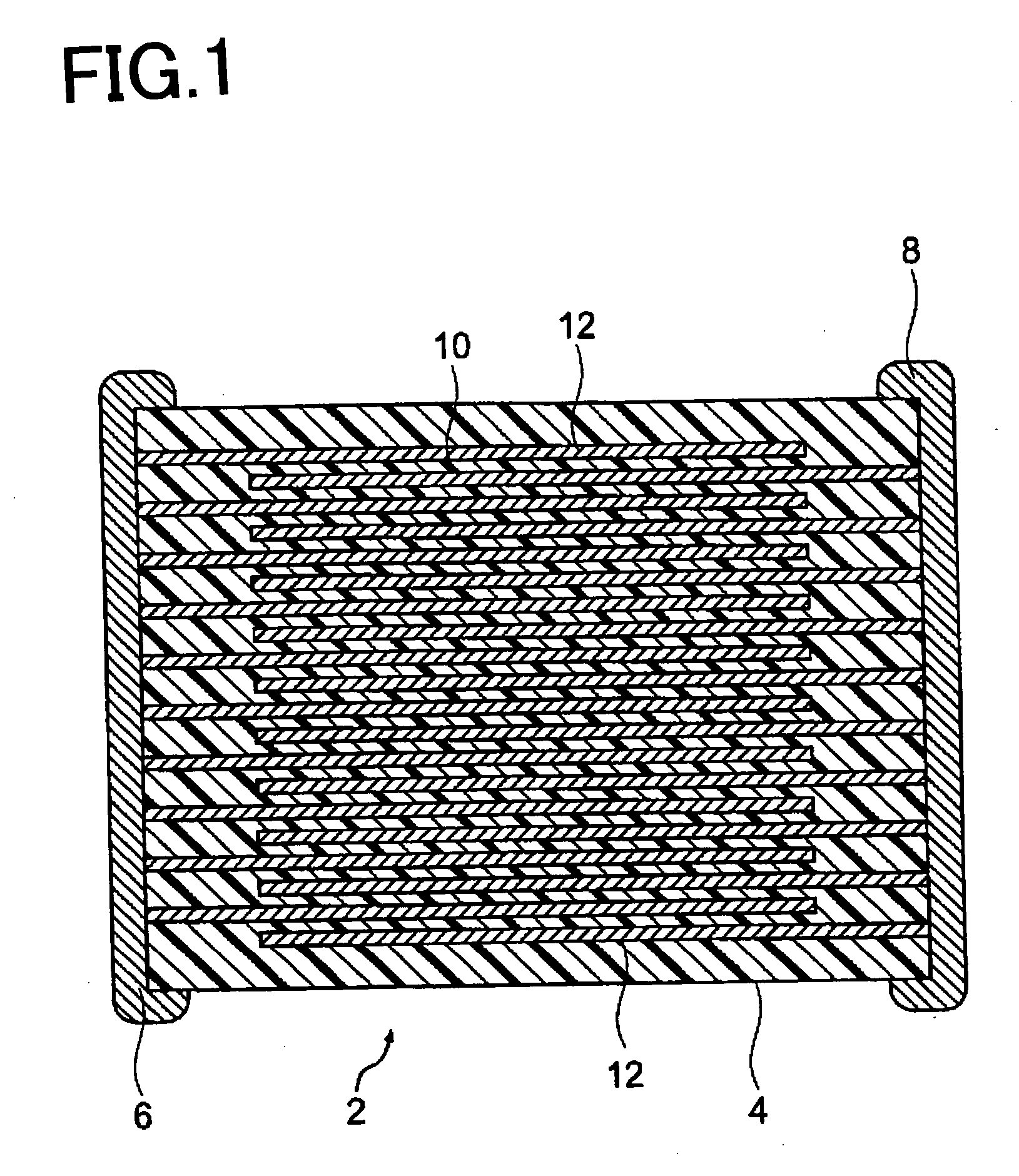
[0051] As shown in FIG. 1, the multilayer ceramic capacitor 2 according to the present embodiment has a capacitor body 4, first end electrode 6, and second end electrode 8. The capacitor body 4 has dielectric layers 10 and internal electrode layers 12. Between the dielectric layers 10, these internal electrode layers 12 are alternately stacked. One of each two alternately stacked internal electrode layers 12 is electrically connected to the inside of a first end electrode 6 formed at the outside of one end of the capacitor body 4. Further, the other of each two alternately stacked internal electrode layers 12 is electrically connected to the inside of a second end electrode 8 formed at the outside of the other end of the capacitor body 4.

[0052] In th...

second embodiment

[0155] In this embodiment, as shown in FIG. 6, inside the drying chamber 62, instead of the metal sheet 84, a roller conveyor 80 is provided along a predetermined range of length L1 from the inlet 62a. The roller conveyor 80 has less contact with the sheet 20 compared with a belt conveyor 82 and helps prevent uneven drying. This is confirmed by experiments of the inventors. The rest of the configuration and the action and effect are similar to those of the first embodiment.

third embodiment

[0156] Further, the present invention may also be configured as shown in FIG. 7. In this embodiment, inside the drying chamber 62, instead of the belt conveyor 82, a roller conveyor 80 is arranged along the long direction under the sheet 20 and guides the sheet 20 in the continuous feed direction Dc.

[0157] In particular, in the present embodiment, not the entire roller conveyor 80 inside the drying chamber 62 contacts the back surface of the sheet 20. At a predetermined range of length L1 from the inlet 62a of the drying chamber 62 to the feed direction Dc, the roller conveyor 80 becomes much lower than the rest of the roller conveyor 80 and does not contact the sheet 20. Alternatively, it is possible to completely eliminate the part of the roller conveyor 80 in this range of length L1. In this embodiment, it is possible to further suppress uneven drying. The rest of the configuration and action and effects are similar to those of the first embodiment.


PUM


Abstract

A printing and drying method comprising laying a support sheet 20 elongated in the long direction so as to bridge both a printing zone 42 and a drying zone 44, in the printing zone 42, giving the support sheet 20 a first tension F1, in that state, printing the support sheet 20 with predetermined patterns, then feeding the support sheet 20 toward the drying zone 44, in the drying zone 44, giving the support sheet 20 on which the predetermined patterns were printed a second tension F2, and in that state, drying it in a drying chamber 62. The first tension F1 and the second tension F2 are given by separate tension giving means, and the second tension F2 is tension given along the support sheet 20 in the long direction and able to prevent shrinkage of the support sheet 20 in the long direction while passing through the drying zone 44.

Description

BACKGROUND OF THE INVENTION [0001] 1. Field of the Invention [0002] The present invention relates to a printing and drying method, a method of production of an electronic device, and a printing and drying system, more particularly relates to a printing and drying method and a printing and drying system enabling overlapping printing of complementary type patterns on a support sheet with little positional deviation when for example producing a multilayer ceramic capacitor or other electronic device. [0003] 2. Description of the Related Art [0004] For example, when producing a multilayer ceramic capacitor or other electronic device, as shown in FIG. 10, sometimes a support sheet constituted by the carrier sheet 20 is formed on its surface with a release layer 22 which in turn is formed over it with predetermined patterns of an electrode layer 12a by printing. Alternatively, sometimes a carrier sheet 20 is formed on its surface with a ceramic green sheet which in turn is formed on its s...

Claims


Application Information

Patent Timeline
IPC IPC(8): B41M1/12H01G13/00
CPCH01G13/04H05K1/0306H05K3/007H05K3/207H05K3/227H05K2203/0156H05K2203/0271H05K2203/1545H04R1/1058
Inventor KANASUGI, MASAAKIISHIYAMA, TAMOTSUSATO, SHIGEKIKARATSU, MASAHIROSUZUKI, TSUNEO
Owner TDK CORPARATION
Why Eureka
Try Eureka