Air core inductive element on printed circuit board for use in switching power conversion circuitries

Inactive Publication Date: 2006-09-28
SEMTECH CORP
View PDF10 Cites 26 Cited by
  • Summary
  • Abstract
  • Description
  • Claims
  • Application Information

AI Technical Summary

Benefits of technology

[0057] The magnetic lines, representing the spatial lines that have equal magnetic field, are closed linking together the two square spiral conductors as shown in the cross section C1 of FIG. 2B. This specific topology for the inductor results in a higher overall inductance because of improved coupling between the two spiral inductors. This improved coupling also lowers the radiated magnetic energy.
[0058] According to another embodiment of the presen

Problems solved by technology

Furthermore the stray magnetic field that generates undesired electromagnetic inte

Method used


Image

  • Air core inductive element on printed circuit board for use in switching power conversion circuitries
  • Air core inductive element on printed circuit board for use in switching power conversion circuitries
  • Air core inductive element on printed circuit board for use in switching power conversion circuitries

Examples


Embodiment Construction

A. FIG. 2A

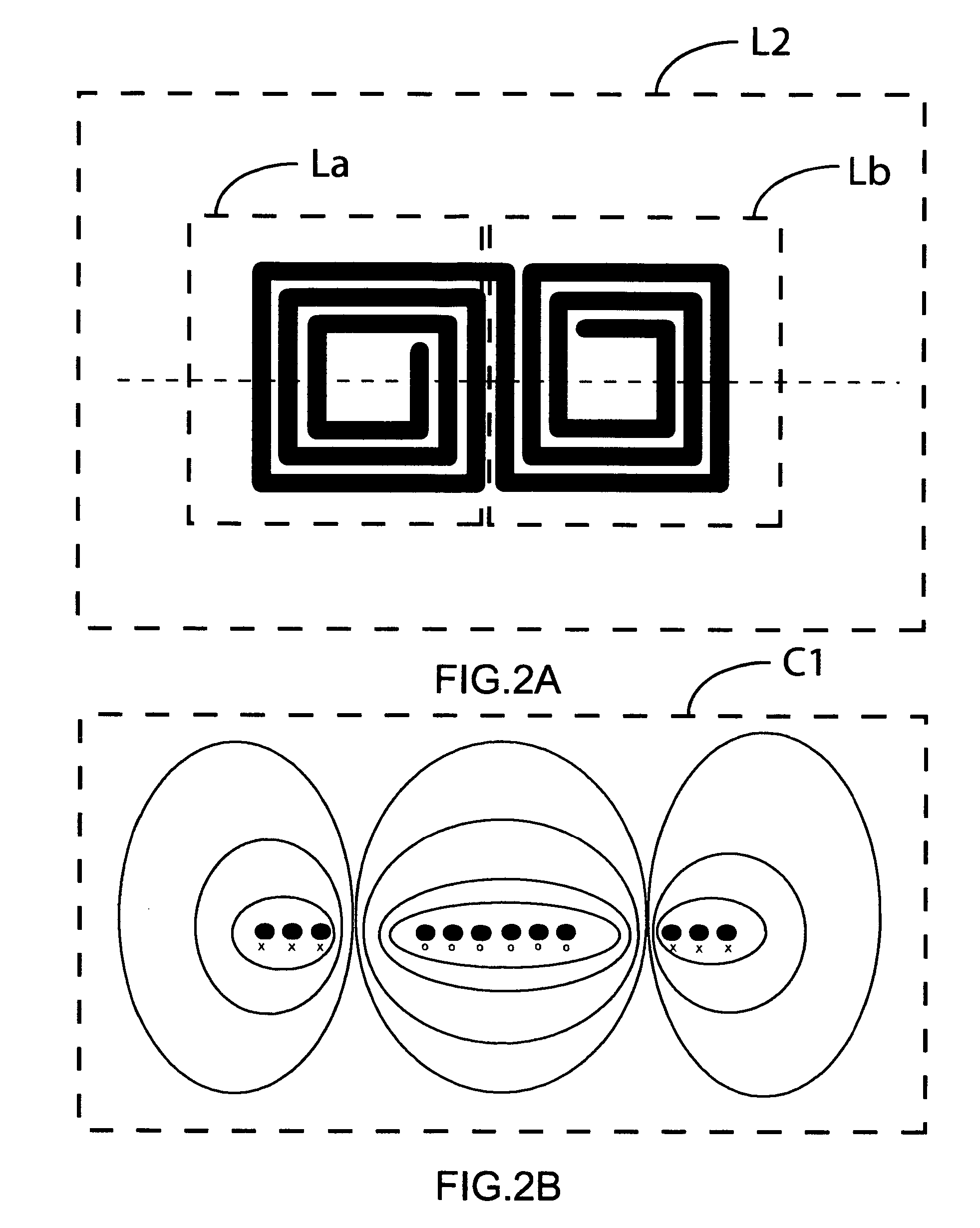
[0068]FIG. 2A is a plan view of an air core inductive element made of a conductive layer on a printed circuit board to which the present invention is applied in a first preferred embodiment.

[0069] The two conductors are printed on one layer of the multi-layer printed board and are electrically connected to each other to form one single inductive element constituted by the series of the two spiral inductors. Namely, the inductor device L2 comprises the paired two spiral formed interconnection structures La and Lb The current is flowing in the two square spiral conductors in opposite direction. If the current is flowing clockwise in one spiral inductor La then it flows counter-clockwise into the spiral inductor Lb such that the two generated magnetic fields can be coupled to each other.

B. FIG. 2B

[0070]FIG. 2B is a cross section of the inductor device L2 of FIG. 2A with the correspondent magnetic lines, representing the spatial lines that have equal magnetic field. The mag...


PUM

PropertyMeasurementUnit
Magnetic fieldaaaaaaaaaa
Sizeaaaaaaaaaa
Flexibilityaaaaaaaaaa

Abstract

A low cost, low EMI air core inductor fabricated on printed circuit board for power conversion circuits is described. The inductive element combines the advantages of high efficiency and minimum board height requirements. It allows high frequency switching without adding undesired magnetic losses and minimizing the electromagnetic interferences in form of radiated energy. The absence of any magnetic layer adds to the simplicity of the manufacturing process resulting in lower cost. This inductive element allows operation for the conventional and higher frequency step-up and step-down switching voltage converters minimizing the size and cost of output capacitors and reducing the output voltage ripple.

Description

BACKGROUND OF THE INVENTION [0001] 1. Field of the invention [0002] The present invention relates to the manufacture of magnetic structures and electric reactive components, and more specifically to an inductor formed on a printed circuit board. [0003] The invention also falls within the field of switching voltage regulators and electronic power supplies, which convert energy from one level to another. These devices have been common in all electronic systems. More specifically, the invention falls into the class of voltage regulators referred to as buck and boost converters, which convert a voltage to a higher or lower voltage. The present invention further relates to passive components structures embedded on a printed circuit board for use in power conversion circuits and techniques. [0004] 2. Brief Description of Related Art [0005] Switching power converters are common systems which typically have an input terminal for receiving an input voltage, and an output terminal which suppl...

Claims


Application Information

Patent Timeline
IPC IPC(8): H01F27/28
CPCH01F17/0006H01F17/0013Y10T29/4902H01F27/346H01F17/02H01F2017/0073
Inventor MENEGOLI, PAOLOSAWTELL, CARL K.
Owner SEMTECH CORP
Why Eureka
Try Eureka