Light-emitting device and display

a technology of light-emitting devices and displays, applied in static indicating devices, instruments, nanoinformatics, etc., can solve problems such as the inability to reproduce color beyond, and achieve the effect of expanding the color-reproduction rang

Inactive Publication Date: 2006-09-28
SANYO ELECTRIC CO LTD
View PDF4 Cites 32 Cited by
  • Summary
  • Abstract
  • Description
  • Claims
  • Application Information

AI Technical Summary

Benefits of technology

[0023] Furthermore, in a configuration capable of performing the above-described full-color video display, it may be configured such that light in certain color, which is at least one of light in red color, light in green color, and light in blue color, of which wavelengths differ each other, is emitted. With the above-described configuration, the pixel may successively between two kinds of light in red color, of which wavelengths differ, although the color as such is red, for example, thus possible to transform the color-reproduction range on a chromaticity diagram into a polygon, which has four or more vertices. This makes it possible to reproduce the colors beyond a conventional triangular-shaped color-reproduction range.
[0024] In addition, in a configuration capable of performing the above-described full-color video display, a display may be configured to appropriately emit light in another color (light in cyan color, light in yellow color, and light in magenta color, for example) other than three colors, that is, red, green, and blue. In such the configuration, too, it is possible to expand the color-reproduction range.

Problems solved by technology

As shown in FIG. 6, a color-reproduction range on a chromaticity diagram takes a triangular form, and it is not possible to reproduce the color beyond this range.

Method used


Image

  • Light-emitting device and display
  • Light-emitting device and display
  • Light-emitting device and display

Examples


embodiment 1

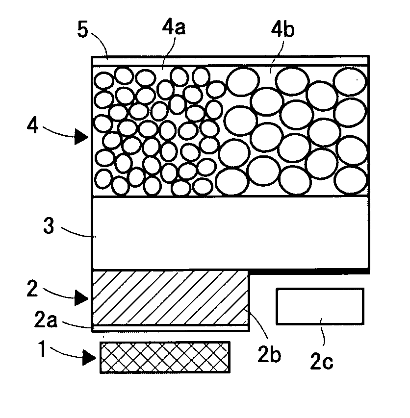
[0031] Hereinafter, a light-emitting element and a direct view-type display according to an embodiment of the present invention will be described based on FIG. 1 to FIG. 5.

[0032]FIG. 1 is a sectional view showing structure of a pixel (structure of a light-emitting element) in a direct view-type display of this embodiment. A plane light source (emitting portion) 1 is a light source for emitting ultraviolet rays, which is excitation light, and is configured to be capable of changing an amount of light guided to each pixel. Such the plane light source 1 may be configured to have backlight formed of a lamp emitting the ultraviolet rays and a light guide plate, and a transmissive liquid crystal panel provided on a light-emission side of this backlight. That is, by changing an applied voltage value to a pixel electrode in the liquid crystal panel, it becomes possible to render variable the amount of light guided to the light-emitting portion within each pixel variable (see FIG. 5).

[0033...


PUM

PropertyMeasurementUnit
photoluminescentaaaaaaaaaa
light-emitting colorsaaaaaaaaaa
electroluminescentaaaaaaaaaa

Abstract

Provided is a light-emitting element, and a direct-view type display, capable of expanding a color-reproduction range. A plain-surface light source (1) is capable of emitting light in an area corresponding to pixels by a variable light-emitting amount. A liquid crystal cell (2b) is formed in such a manner as to correspond to each pixel on the plain-surface light source (1). On the liquid crystal cell (2b), a birefringent plate (3) is provided. On the birefringent plate (3), a quantum dot layer (4) is formed. The quantum dot layer (4) is coated in such a manner as to have a first quantum dot layer (4a) (grain size A), and a second quantum dot layer (4b) (grain size B: A<B). During a 1-field period, it is possible to form a state that ultraviolet rays are guided only to the first quantum dot layer (4a) a state that the ultraviolet rays are guided to the both dot films (4a), (4b) at an arbitrary ratio, and a state that the ultraviolet rays are guided only to the second quantum dot layer (4b). This, in a case of light in red color, allows each of pixels for respective colors to create light in red color in which different red colors are mixed, for example.

Description

TECHNICAL FIELD [0001] The present invention relates to a light-emitting element and a display. BACKGROUND ART [0002] As a direct-view-type display-use panel, a liquid crystal display panel, a plasma display panel, and others have been known. In the liquid crystal display panel, applied voltage to pixel electrodes are controlled, thus an amount of light to be transmitted is controlled by each pixel. This allows amounts of light of R (red) pixels, G (green) pixels, and B (blue) pixels to differ, which results in a desired color being reproduced. In addition, in the plasma display panel, the number of applications of the voltage to the electrode (the number of sustain discharges between an X electrode and a Y electrode) so as to control a light-emitting amount, which renders different the light-emitting amounts of the R pixels, the G pixels, and the B pixels to differ. As a result, the desired color is reproduced. [0003] It is noted that a colored light-emitting diode using quantum do...

Claims


Application Information

Patent Timeline
Patent Type & Authority Applications(United States)
IPC IPC(8): G09G3/36C09K11/01H01L33/00H01L33/50
CPCB82Y10/00B82Y30/00C09K11/01Y02W30/50
Inventor KUROSAKA, YOSHITAKA
Owner SANYO ELECTRIC CO LTD
Why Eureka
Try Eureka