
Arrangement for the illumination of an image plane

Inactive Publication Date: 2006-09-28
CARL ZEISS JENA GMBH
View PDF4 Cites 38 Cited by
  • Summary
  • Abstract
  • Description
  • Claims
  • Application Information

AI Technical Summary

Benefits of technology

[0010] Proceeding from the above-described disadvantages of the prior art, it is the primary object of the invention to further develop an arrangement for the homogeneous illumination of an image plane in such a way that it is possible to improve the delimitation of the angular distribution at the light outlet and to improve the homogeneous illumination of the image plane by reducing technological costs with respect to the arrangement combined with a cost reduction for the illumination unit in its entirety.
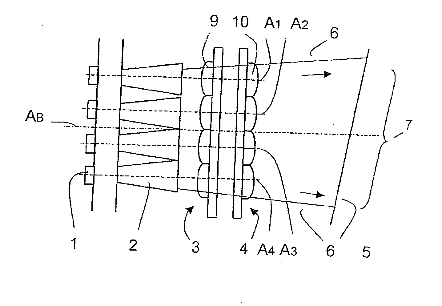
[0013] It is advantageous when two microlens arrays which are arranged one behind the other are characterized by identically constructed, regular arrangements of microlenses, which arrangements lie parallel to one another and in a mirror-inverted manner relative to one another, wherein the microlenses whose optical axes lie parallel to the optical axis of the illumination optics have raised functional surfaces.
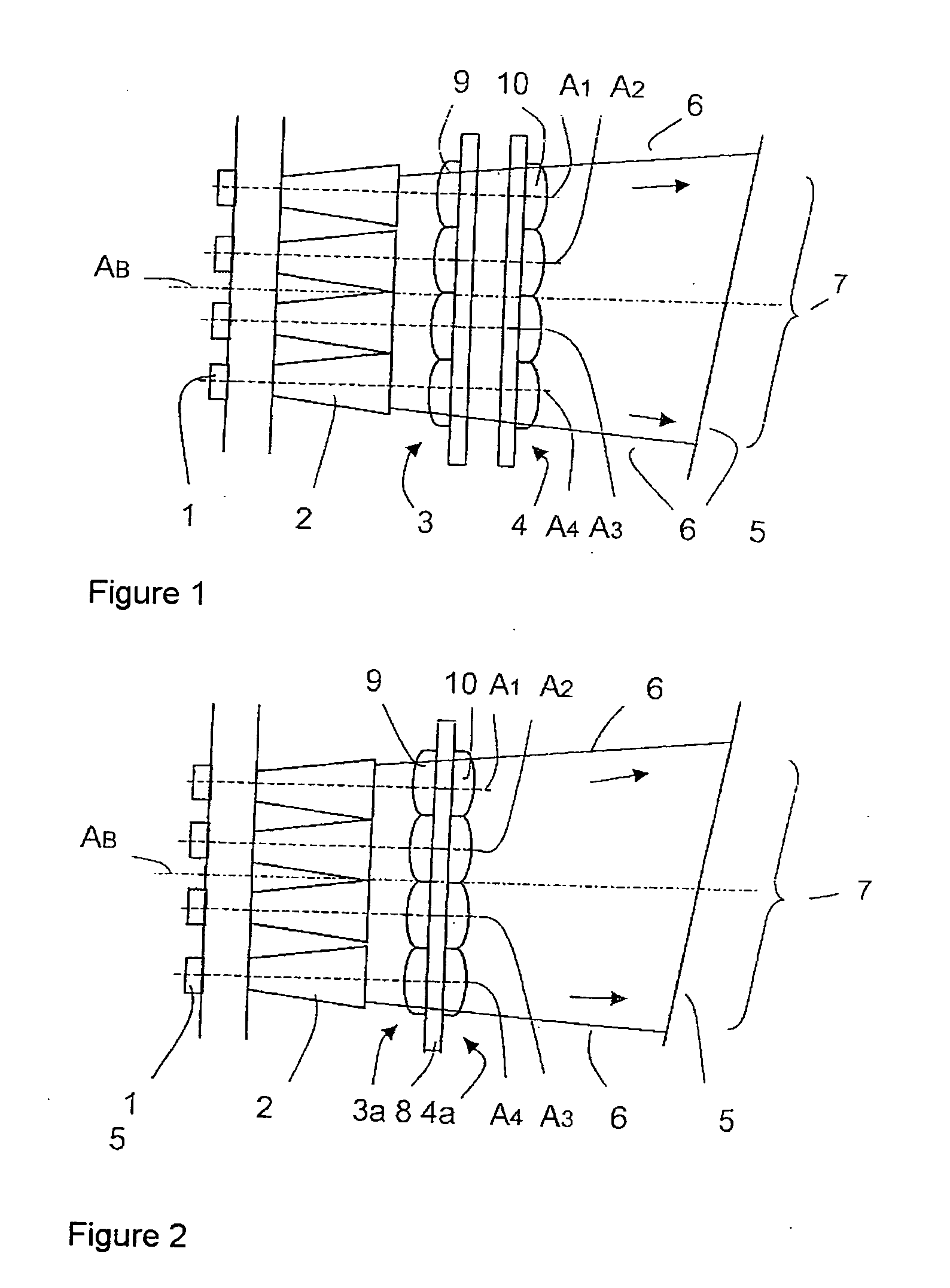
[0017] An advantageous further development of the arrangement consists in that the two microlens arrays are made from one component (twofold microlens array). This reduces the quantity of individual elements and, therefore, also the assembly cost.
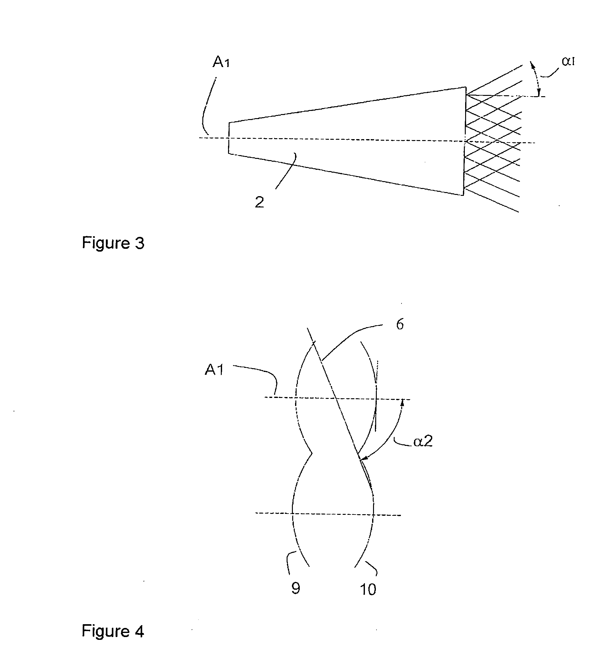
[0019] In another embodiment form, the microlenses are constructed so as to be cylindrical and rectangular, and the microlenses of the first array are arranged so as to be oriented at a 90-degree offset (crosswise) to the microlenses of the second array. In this way, the light is homogenized in the x-direction and y-direction. The substantial advantage of this variant consists in the reduced manufacturing cost as a result of less strict tolerances in the alignment and centering of the microlens arrays.
[0020] Further, it can be advisable to arrange the arrays in such a way that the microlenses of neighboring rows of microlenses are arranged so as to be displaced by one half of their length. This improves field homogeneities particularly in relatively large lenses.
[0027] The inventive arrangement of the illumination optics in an array, a subsequent integrator array, and the lens arrangements having at least two arrays obviate the need for collecting optics for homogenization and intensity profiling, so that the arrangement is more economical and compact compared to the solutions of the prior art. Moreover, by adapting the illumination angles to the acceptance angles of the subsequent system, the efficiency of the system is increased and, by reducing stray light components, contrast is increased.

Problems solved by technology

However, they have the disadvantage that neither the angular area nor the surface of the image-generating element is illuminated in a completely homogeneous manner.
This is further complicated by the fact that hollow integrators are not particularly efficient because of the inner reflecting surfaces.
Further, it is very difficult in terms of technique to coat hollow integrators having lengths over 10 mm from the inside.
Yet, the requirement for homogeneous illumination of surfaces and angles necessarily leads to longer integrators.
In systems in which the light emergence angles vary in x-direction and y-direction and in which high efficiency is demanded, it is very complicated to achieve a homogeneous, well-defined angular distribution.
The disadvantage in the use of integrator arrays consists in the high manufacturing cost required to achieve a high positioning accuracy of the individual integrators, so that components of this type are very cost-intensive.

Method used


Image

  • Arrangement for the illumination of an image plane
  • Arrangement for the illumination of an image plane
  • Arrangement for the illumination of an image plane

Examples


Embodiment Construction

[0045]FIG. 1 is a schematic view of the arrangement according to the invention with illumination optics 1 comprising an LED array, an integrator array 2, two microlens arrays 3 and 4, and an image-generating element 5.

[0046] The light emitted by the individual LEDs of the illumination optics 1 first reaches the associated integrators of the integrator array 2. Through the multiple reflections in the integrators, the light components are homogenized when passing through the integrator array 2 and the light outlet surfaces are illuminated homogeneously. Due to the arrangement of the microlens arrays 3 and 4 downstream, these microlens arrays 3 and 4 comprising two identically constructed, regular arrangements of identical lenses with raised surfaces, which arrangements are parallel to one another and mirror-inverted with respect to one another, the optical axes A1, A2, A3 and A4 of the lenses extending parallel to the optical axis AB of the illumination optics 1, the areas of the rad...


PUM


Abstract

The invention is directed to an arrangement for the homogeneous illumination of an image plane, preferably for application in a head-up display in a motor vehicle, comprising illumination optics having an array of emitters with a broad emitting characteristic, for example, an arrangement of luminescent diodes (LEDs, OLEDs), an integrator array, and an image-generating element, and the optical axis of an emitter is associated with the mechanical axis of an integrator of the integrator array. According to the invention, at least two microlens arrays are provided for the purpose of achieving an angular homogeneity of the rays exiting from the integrator array on the illuminated area of the image-generating element at the light outlet of the integrator array.

Description

CROSS-REFERENCE TO RELATED APPLICATIONS [0001] This application claims priority of German Application No. 10 2005 013 950.7, filed Mar. 26, 2005, the complete disclosure of which is hereby incorporated by reference. BACKGROUND OF THE INVENTION [0002] a) Field of the Invention [0003] The invention is directed to an arrangement for the homogeneous illumination of an image plane, preferably for application in a head-up display (HUD) in a motor vehicle, comprising illumination optics having an array of emitters with a broad emitting characteristic, for example, an arrangement of luminescent diodes (LEDs, OLEDs), an integrator array, and an image-generating element, and the optical axis of an emitter is associated with the mechanical axis of an integrator of the integrator array. [0004] b) Description of the Related Art [0005] Head-up displays are known and are increasingly offered as accessories in particular vehicle models. A virtual image of an object to be displayed is generated and,...

Claims


Application Information

Patent Timeline
IPC IPC(8): F21V1/00
CPCG02B3/0031G02B3/005G02B3/0056G02B3/0062G02B3/0068G02B27/0101G02B27/0961G02B27/0994G02B2027/0123G03B21/14G03B21/208
Inventor MENZEL, EVA-MARIATROELLSCH, ARNEDEGEN, ARTUR
Owner CARL ZEISS JENA GMBH
Learn More