
Method and apparatus for coordinating a wireless PAN network and a wireless LAN network

a wireless pan network and wireless lan technology, applied in the field of wireless communications, can solve the problems of reducing the seamless user experience, burdening and annoyance of users, and additional concerns, and achieve the effect of less power

Inactive Publication Date: 2006-09-28
ATMEL WI FI SOLUTIONS
View PDF16 Cites 246 Cited by
  • Summary
  • Abstract
  • Description
  • Claims
  • Application Information

AI Technical Summary

Benefits of technology

[0027] The secondary network (PAN) protocols might use synchronization and traffic scheduling methods to meet the power and latency requirements of specific wireless PAN applications. Such methods allow wireless PAN devices to agree on an inactivity time, during which at least part of the circuitry can be disabled, wherein disabling is such that less power per unit time is consumed by the network circuit relative to power consumed when not disabled.

Problems solved by technology

The latter is a burden and annoyance to the user and can significantly reduce the seamless user experience.
Weight and complexity are additional concerns in many wireless communication systems.
The use of different technologies for WLAN and wireless PAN connectivity increases cost, weight and power usage (at the COORD side and / or the PER side), and impairs a seamless user experience.
However, PAN nodes are often very power-sensitive devices.
Instead, small batteries with limited power capacity are used.
Such peripherals cannot typically support the power usage requirements typical of WLAN wireless circuitry, such as 802.11x circuitry.
A host of other difficulties are present in view of the optimizations, goals and designs of differing network protocols.
Another drawback is that independent LANs and PANs may interfere if they share a common frequency band.

Method used


Image

  • Method and apparatus for coordinating a wireless PAN network and a wireless LAN network
  • Method and apparatus for coordinating a wireless PAN network and a wireless LAN network
  • Method and apparatus for coordinating a wireless PAN network and a wireless LAN network

Examples


Embodiment Construction

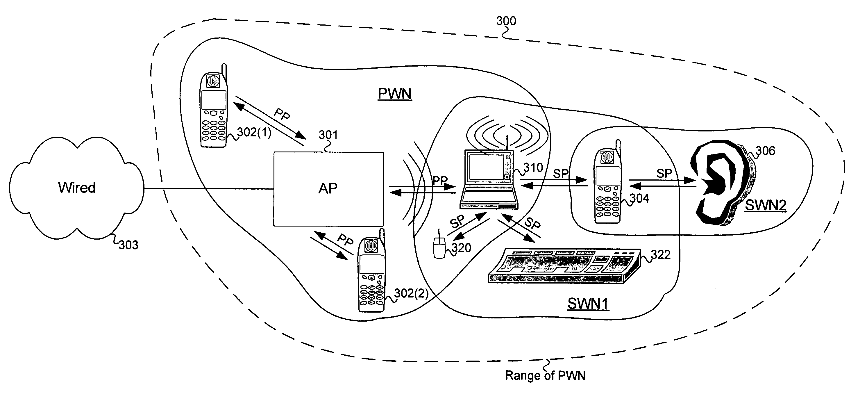
[0047] The present disclosure describes methods and apparatus for operating a secondary wireless network (“SWN”) in the presence of a primary wireless network (“PWN”), including features, elements, configurations and / or programming that allow for co-existence of SWN devices in a space where PWN traffic might occur, as well as features, elements, configurations and / or programming that include coordination between a PWN and an SWN (or pluralities of these) such that a device might handle traffic for each of the networks present.

[0048] For example, a computing device might have a common network interface that allows the computing device to be a node in the PWN and a node in the SWN. In a particular example, a computing device is an 802.11x STA that is a member of a PWN capable of associating with and communicating with an AP for that PWN (as well as possibly other devices in that PWN) using a network interface while also elements of that same network interface are used to simultaneous...


PUM


Abstract

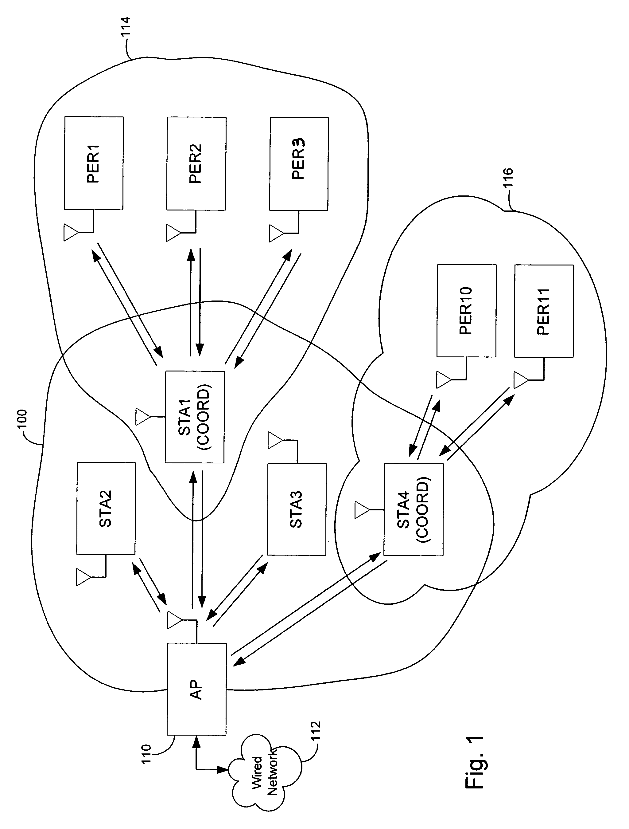
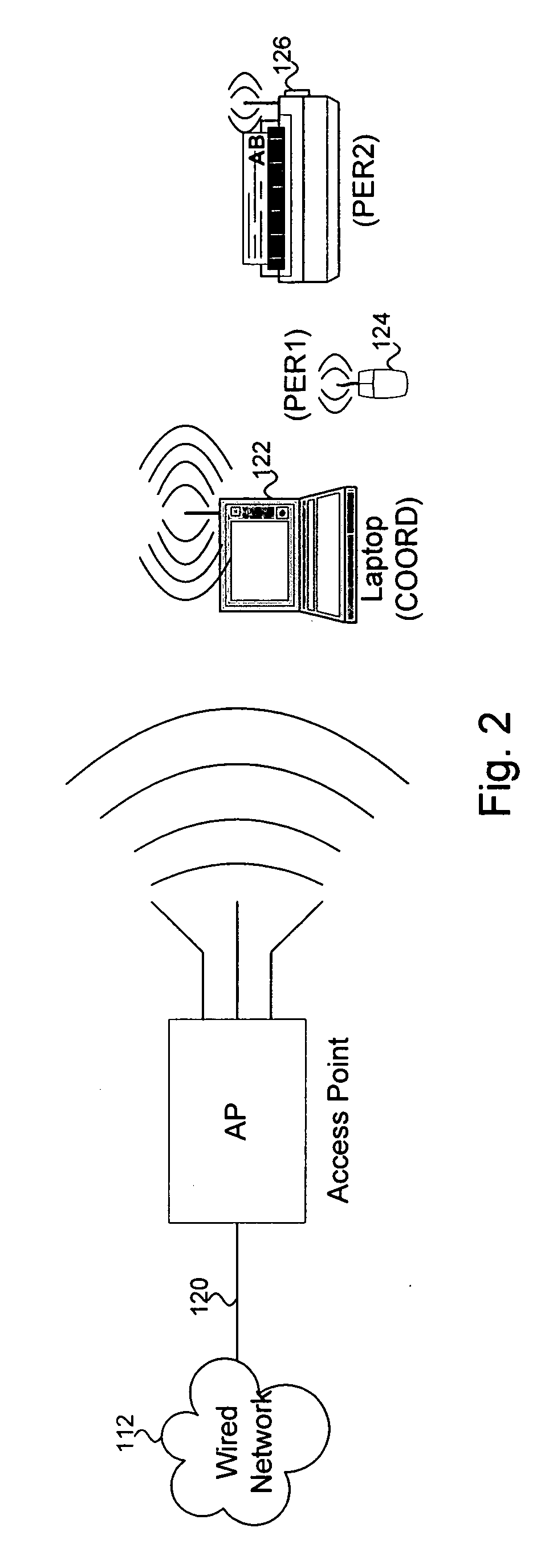
Devices of a personal area network (PAN) use a wireless medium that is shared with a wireless local area network (WLAN). WLAN devices communicate using protocols of the WLAN and PAN devices communicate using PAN protocols allowing for lower power transmissions over the wireless medium relative to transmissions over the WLAN. A PAN coordinator device obtains access to the wireless medium for the PAN devices by signalling a reservation of the medium by the PAN coordinator device, such that the other devices defer use of the wireless medium, including at least one WLAN device, for a reservation period. During the reservation period, the communication is done using the PAN protocol. The signalling can be implicit in that the PAN coordinator device transmits one or more frame using the PAN protocol but that is at least partially understandable by WLAN devices such that they defer upon receipt of one or more of the PAN protocol frames, which may be a standard or modified HCCA-CF poll frame, a CTS frame with an increased duration field, or other variation. A PAN coordinator might also signal an access point to set up a DLS link between the PAN coordinator and itself and use the DLS period for PAN traffic.

Description

CROSS-REFERENCES TO RELATED APPLICATIONS [0001] This application claims the benefit of and is a non-provisional of U.S. patent application Ser. No. 60 / 661,746 filed on Mar. 14, 2005, which is incorporated by reference in its entirety for all purposes.FIELD OF THE INVENTION [0002] The present invention relates generally to wireless communications and more particularly to coordinating different network uses of a common wireless medium. BACKGROUND OF THE INVENTION [0003] Wireless communication among electronic devices has been increasing as the benefits and conveniences of wireless communication become more preferred. A wireless communication system or wireless network is often described as containing nodes (or more precisely, circuitry associated with the concept of a node) and a wireless medium (WM) over which the nodes' circuitry communicate to convey information. Where some action or activity is described as happening at (or being done at) a node, it should be understood that the e...

Claims


Application Information

Patent Timeline
Patent Type & Authority Applications(United States)
IPC IPC(8): H04Q7/00H04Q7/24H04W28/26H04W72/12H04W84/10H04W84/12H04W84/20H04W84/22H04W88/04H04W88/06H04W88/10H04W92/02
CPCH04W28/26H04W72/12H04W84/10H04W84/12H04W84/20Y02B60/50H04W88/04H04W88/06H04W88/10H04W92/02H04W84/22H04W52/0209Y02D30/70H04W74/06H04W84/18
Inventor VLEUGELS, KATELIJNPEETERS, ROEL
Owner ATMEL WI FI SOLUTIONS
Learn More