Test system and method for parallel modulation error measurement of transceivers

a transceiver and error measurement technology, applied in the field of parallel modulation error measurement of transceivers, can solve the problems of only being able to test the precision receiver, reducing the test time or test cost of the integrated transceiver, and expensive test instruments for precision receivers and precision sources

Active Publication Date: 2006-09-28
KEYSIGHT TECH
View PDF21 Cites 30 Cited by
  • Summary
  • Abstract
  • Description
  • Claims
  • Application Information

AI Technical Summary

Benefits of technology

[0008] By utilizing a loop-back test configuration, the test system requires only a single precision source to measure both the demodulation and modulation errors of a radio transceiver, thus eliminating the need for precision rece

Problems solved by technology

However, with the integration of transmitters and receivers onto a single chip, the ability to test multiple receivers in parallel does not result in a decrease in test time or test cost of integrated transceivers.
Both the precision rece

Method used


Image

  • Test system and method for parallel modulation error measurement of transceivers
  • Test system and method for parallel modulation error measurement of transceivers
  • Test system and method for parallel modulation error measurement of transceivers

Examples


Embodiment Construction

[0018] Common transceiver tests include error-vector magnitude (EVM) for transmitter modulation and receiver demodulation accuracy, signal to noise and distortion (SINAD) for the receiver adding unwanted signals, and spectral mask for the transmitter adding unwanted signals. In general, EVM is a measure of signal quality, and provides a mechanism for uncovering at least some of the underlying causes of signal impairments and distortion.

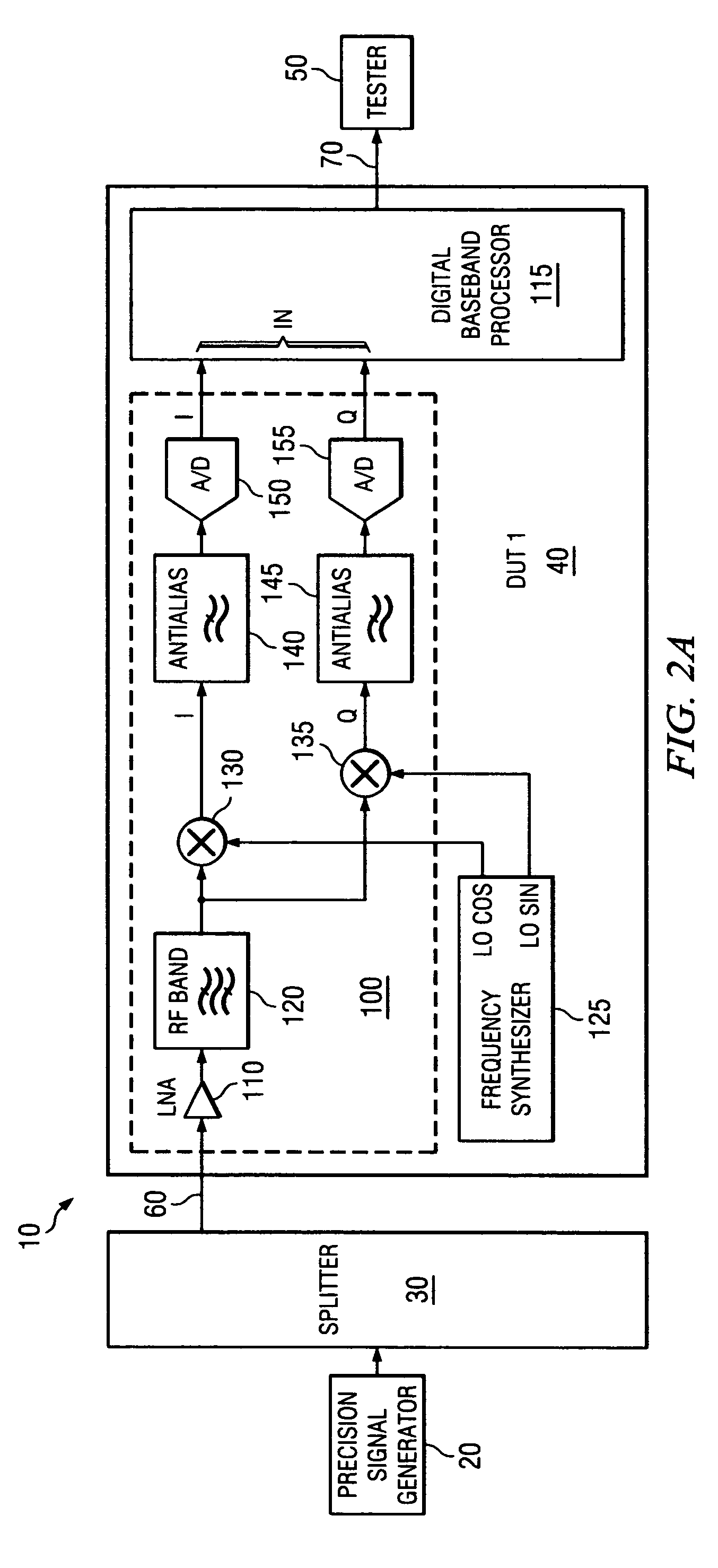
[0019] Transceivers modulate signals onto a sinusoidal carrier by varying both its amplitude and phase using a process known as vector modulation. This modulation process typically includes multiple combinations of amplitude and phase, where each combination is referred to as a symbol. When displayed in polar coordinates of amplitude and phase or in rectangular coordinates of in-phase (I or cosine) component and quadrature (Q or sine) component these symbols form a regular arrangement referred to as a constellation. Each symbol has an ideal position ...


PUM


Abstract

A test system is capable of performing parallel modulation error measurement of transceivers using a loop-back configuration. Each transceiver includes a transmitter and a receiver. A signal generator generates a first modulated signal for input to the receivers of the transceivers. A tester is operable to measure a first demodulation error produced by the receiver in response to the first modulated signal and to measure a modulation error of the transmitter based on the first demodulation error and a second demodulation error. The second demodulation error is produced by the receiver in response to a second modulated signal generated by the transmitter and coupled from the transmitter to the receiver.

Description

BACKGROUND OF THE INVENTION [0001] Each wireless communication device, such as a cellular telephone, two-way radio, personal digital assistant (PDA), pager, personal computer (PC), laptop computer, home entertainment equipment, etc., either includes a built-in radio transceiver (i.e., receiver and transmitter) or is coupled to an associated radio transceiver (e.g., a station for in-home and / or in-building wireless communication networks, RF modem, etc.). Radio transceivers are currently being integrated, in System-on-Chip (SoC) or System-in-Package (SiP), to reduce cost, size, and power, and to increase functionality. One consequence of this integration is reduced test access to the radio system's functional blocks (e.g., individual transmitter and receiver blocks). Traditionally, radio transceiver testing has relied on separate testing of each transmitter and parallel testing of multiple receivers. Thus, receiver testing has generally enjoyed the benefits of reduced test time and r...

Claims


Application Information

Patent Timeline
IPC IPC(8): H04B17/00H04B1/38H04J3/14
CPCH04L1/206H04L1/243
Inventor O'NEILL, PETER MARK
Owner KEYSIGHT TECH
Why Eureka
Try Eureka