Fiber optic sensing device and method of making and operating the same

a fiber optic and sensing device technology, applied in the field of fiber optic sensing devices, can solve the problems of limited operation temperature range, limited conventional sensing device, and limited temperature range of conventional sensing devices

Inactive Publication Date: 2006-09-28
GENERAL ELECTRIC CO
View PDF10 Cites 36 Cited by
  • Summary
  • Abstract
  • Description
  • Claims
  • Application Information

AI Technical Summary

Problems solved by technology

However, such conventional sensing devices are limited by the operational conditions in which they may be employed.
For example, conventional sensing devices are often limited to relatively mild temperature conditions and, as such, limited operational temperature ranges.
Indeed, conventional devices are limited to temperatures between +80° C. to +250° C., depending upon the fiber grating coating materials.
As such, it is difficult to measure temperatures for components in high-temperature environments like turbines and engines.
The sensing devices for gas components such as NOx, CO and O2 also have a similar limitation in terms of accuracy and spatial resolution.
Accordingly, conventional sensing devices present limitations when employed in high temperature and / or harsh environments such as, gas / steam turbine exhausts, coal-fired boilers, aircraft engines, downhole applications and so forth.
However, it is difficult to simultaneously detect multiple parameters, such as temperature and gas, through a single conventional Bragg grating sensing element.
Such separation of sensed parameters is conventionally a difficult and time-consuming process.
Moreover, such systems require overwriting gratings at the same fiber location, which often present difficulties during the manufacturing the fiber grating for the sensor.
In summary, conventional Bragg grating sensors do not facilitate discernment of what environmental or elemental factor influenced the sensor, rather only the physical changes in the sensor itself are readily detectable.

Method used


Image

  • Fiber optic sensing device and method of making and operating the same
  • Fiber optic sensing device and method of making and operating the same
  • Fiber optic sensing device and method of making and operating the same

Examples


Embodiment Construction

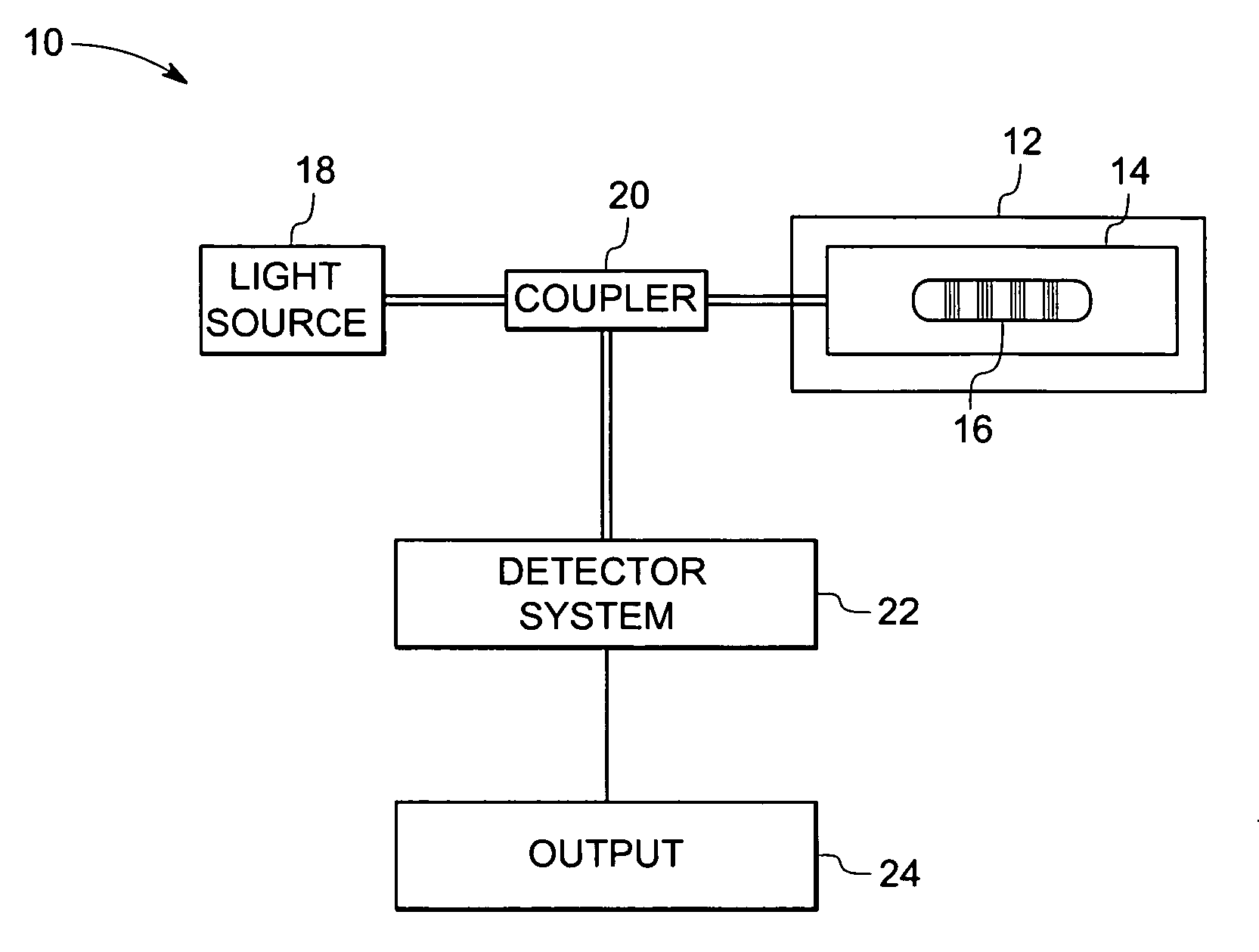
[0024] Referring now to drawings, FIG. 1 illustrates an exemplary fiber optic sensing system 10 for detecting parameters of an environment and / or object 12. Although the present discussion focuses on sensing devices and systems, the present technique is not limited to sensing field, but is also applicable to other modalities, such as, optical filters, data transmission, and telecommunications, among others. Accordingly, the appended claims should not be limited to or by the exemplary embodiments of the following discussion. The fiber optic sensing system 10 includes a fiber optic sensing device 14 that, in turn, includes a grated cable 16. As illustrated, the cable 16 is disposed within the element 12, causing changes in the element 12 to translate to the cable 16. The grated cable 16 includes a core that has a plurality of grating elements arranged in an aperiodic pattern, which is described in detail below. In the present discussion, a grating element refers to a variance in the i...


PUM


Abstract

In accordance with one exemplary embodiment the invention provides a multi-parameter fiber optic sensing system with an aperiodic sapphire fiber grating as sensing element for simultaneous temperature, strain, NOx, CO, O2 and H2 gas detection. The exemplary sensing system includes an aperiodic fiber grating with an alternative refractive index modulation for such multi-function sensing and determination. Fabrication of such quasiperiodic grating structures can be made with point-by-point UV laser inscribing, diamond saw micromachining, and phase mask-based coating and chemical etching methods. In the exemplary embodiment, simultaneous detections on multi-parameter can be distributed, but not limited, in gas / steam turbine exhaust, in combustion and compressor, and in coal fired boilers etc. Advantageously, the mapping of multiple parameters such as temperature, strain, and gas using sapphire aperiodic gratings improves control and optimization of such systems directed to improve efficiency and output and reduce emissions.

Description

BACKGROUND [0001] The present invention relates generally to fiber optic sensing devices, and more particularly, to a fiber optic sensing device for detecting multiple parameters in an environment or element, for example. Indeed, the present invention provides advantages related to the use of fiber optic sensing devices in harsh environments, for instance. [0002] Various sensing devices are known and are generally in use. For example, thermocouples are used for measuring the temperature in components of a device, such as exhaust systems, combustors, compressors and so forth. Yet other sensing systems are employed to detect physical parameters such as, strain or temperature in an infrastructure. As one example, Bragg grating sensors are often employed. However, such conventional sensing devices are limited by the operational conditions in which they may be employed. For example, conventional sensing devices are often limited to relatively mild temperature conditions and, as such, lim...

Claims


Application Information

Patent Timeline
Patent Type & Authority Applications(United States)
IPC IPC(8): G02B6/34G02B6/16G02B6/26G02B6/00
CPCG01D5/35303G01N21/774G02B6/02147G02B6/02123G02B6/02085G01D5/35358G01D5/35383B26B5/001B26B29/06
Inventor MCCARTHY, KEVIN THOMASDENG, KUNG-LI JUSTINXIA, HUAKROK, MICHAEL JOSEPHTAWARE, AVINASH VINAYAK
Owner GENERAL ELECTRIC CO
Why Eureka
Try Eureka