Compact superconducting current limiting component in coil configuration with low inductance

Inactive Publication Date: 2006-09-28
NEXANS
View PDF6 Cites 10 Cited by
  • Summary
  • Abstract
  • Description
  • Claims
  • Application Information

AI Technical Summary

Benefits of technology

[0023] In view of the above it was the object of the present invention to provide a superconducting current limiting component with a shunt which makes possible to build up sufficiently high electrical field along the superconducting material during the short circuit, within a short time, which can be produced in a simple and cheap way, and which is capable to create a magnetic field high enough to bring the superconductor material to homogenous quench in the short circuit case. Further, it was the object of the present invention to provide a superconducting current limiting component with a space saving low inductive element design which is easily to be insulated even with respect to high voltages.
[0029] According to the present invention, due to the coil configuration with the same component height the superconductor length can be significantly increased as compared to the superconductor length of the conventional current limiting device having a tube shaped configuration.
[0031] In the default case the resistance appearing in the htsc coil due to the fault current causes a part of the current to by-pass into the shunt coil which is provided around the outer surface of the htsc coil and is connected electrically and physically in parallel with the htsc coil. The magnetic field associated with this current, serves to bring the superconductor material in a uniform quench during the short circuit event and to avoid material degradation, for example, due to hot spot formation.

Problems solved by technology

However, since in bifilar coils input and exit for the current are close together, in particular with respect to high voltage applications insulation is problematical.

Method used


Image

  • Compact superconducting current limiting component in coil configuration with low inductance
  • Compact superconducting current limiting component in coil configuration with low inductance

Examples


example

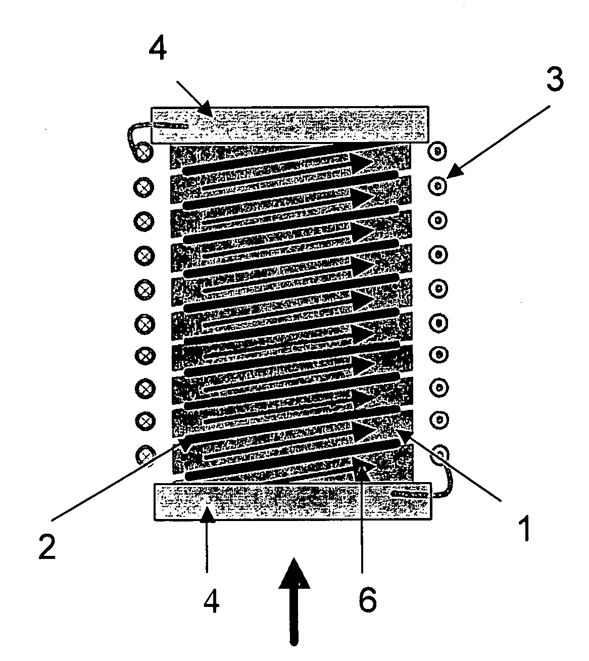
[0103] A superconducting current limiting component according to the present invention is designed for operation at the following conditions:

rated current:600 A, 3-phasenominal voltage:10 kVlimited current:3-4 times the rated current

htsc coil 1:

[0104] A htsc coil is prepared from a melt cast BSCCO-2212 tube having an outer diameter of 25 mm, tube length of 30 cm with 40 mm contacts included having an electrical field of 5 V / cm in the short circuit case and Jc=5000 A / cm2 at 65 K. The details are as follows:

[0105] required critical current (DC) for a rated current of 600 A =>1000 A.

[0106] cross section of the superconductor (coil 1): 1000 A / 5000 A / cm2=20 mm2

wall thickness of the tube:2 mmpitch of the coil:10 mmgap of cutting:1 mmturns260 mm / 11 mm = 23 turnshts conductor length:23 × 76 mm = 175 cmvoltage / component:175 cm × 5 V / cm = 875 Volts
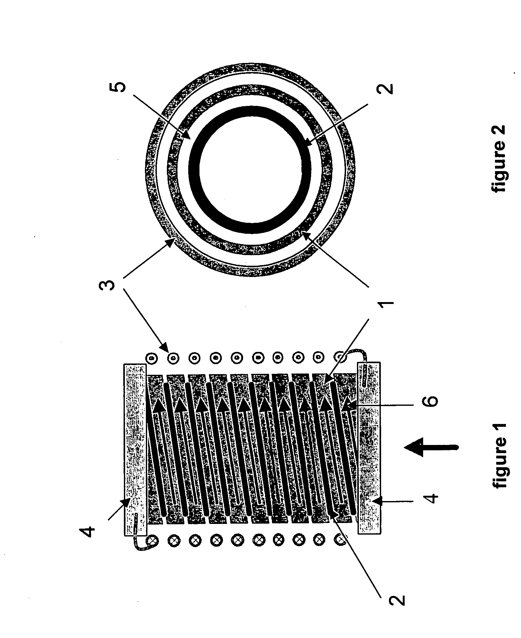
[0107] htsc tube 2:

[0108] melt cast BSCCO-2212 (as for htsc coil 1)

induced current:23 × 600 A = 13.8 kAcritical current:23 kAlength of tub...


PUM


Abstract

The present invention is directed to a superconducting current limiting component, particularly to a ceramic high temperature superconducting current limiting component which is self triggering, comprising a coil (1) made of ceramic high temperature superconductor material, wherein around the outer surface of the coil (1) made of ceramic high temperature superconductor material a second coil (3) is applied as a shunt and, preferably, wherein the coil (1) made of ceramic high temperature superconductor material is applied onto a hollow cylindrical body (2) made of a ceramic high temperature superconductor material.

Description

RELATED APPLICATION [0001] This application is related to and claims the benefit of priority from, European Patent Application No. 05 300 030.3, filed on Jan. 12, 2005, the entirety of which is incorporated herein by reference. FIELD OF THE INVENTION [0002] The present invention relates to a superconducting current limiting component, particularly to a resistive ceramic high-temperature superconducting current limiting component which is self-triggering. BACKGROUND [0003] Superconductors, in particular ceramic high-temperature superconductors, offer a great potential as fault current limiters which enable rapid and effective current limitation, automatic recovery, negligible impedance during normal operation and application at high voltage. [0004] Current limiters based on high-temperature superconducting materials make use of the property of superconducting materials to switch from their superconducting state with essentially no resistance to a normal conductive state when at least...

Claims


Application Information

Patent Timeline
IPC IPC(8): H01L39/00
CPCH01F6/02H01F6/06H01F2006/001H01L39/16H10N60/30
Inventor BOCK, JOACHIMELSCHNER, STEFFENBREUER, FRANK
Owner NEXANS
Why Eureka
Try Eureka