Expandable spring loaded acetabuler reamer

a technology of acetabuler and reamer, which is applied in the field of expandable spring loaded acetabuler reamer, can solve the problems of increasing the risk of contamination and infection of large number of hardware by the operating room staff, requiring the exchange of multiple reamer cups, and time-consuming and labor-intensive to achieve the effect of increasing the diameter of the reamer cup

Inactive Publication Date: 2006-09-28
TERMANINI ZAFER
View PDF11 Cites 113 Cited by
  • Summary
  • Abstract
  • Description
  • Claims
  • Application Information

AI Technical Summary

Benefits of technology

[0008] It is an advantage of the present invention to provide a new and improved expandable acetabular reamer, which will eliminate the need during a hip surgical procedure to exchange a large number of acetabular cups in order to ream the appropriate size cavity in the acetabular bone
[0009] In the present invention, the conventional acetabular reamer cup is replaced by four convex segments that expand in a symmetric and concentric fashion around a reamer shaft with a longitudinal axis and opposite ends. Said convex segments are located at the distal end of the Reamer shaft. In the closed position, the four segment edges are in touch and form a hemispherical cup. Each of the segments is solidly attached to a guiding shaft vertically situated in the center of the segment. Said shaft glides in a tunnel located at the body of the distal part of the Reamer tool. The tunnels of two diametrically opposed cups (1 and 3) are positioned at a 45-degree angle to the longitudinal axis of the Reamer tool. In addition, these two tunnels are located in two co-adjacent planes and next to each other. When said guiding shaft is pushed outward through the tunnel, it drives the convex segment outward. When all four segments are pushed out in a concentric fashion, they will increase the diameter of the reamer cup. To allow this synchronized expansion, each convex segment is solidly attached through a hinge to the distal end of a driving lever. Said driving lever is attached proximally to a sleeve located around the central portion of the Reamer tool. The sleeve is pushed forward by a spring located within the sleeve and wrapped around the center core of the reamer tool. When said sleeve is pushed forward by the spring as described above, it will advance to the driving levers and expand the four spherical quadrant segments in a synchronized fashion similar to the opening mechanism of an umbrella. It is also the object of this invention to provide a full reaming perimeter by the cup. When expansion occurs there will be an area in the center of the cup that is not covered by the reaming segments. In order to provide hemi-circumferential reaming, there has been provision for extension tabs located at the tip of two diametrically opposed convex on segments. In the present improved invention the number of extension tabs is limited to two tabs, however in other embodiments the number of tabs can be greased by pair and may interlace to provide a full hemispherical reaming surface.
[0010] It is also an object of the invention to provide a mechanism, which allow to precisely control the synchronized expansion of the cup. Such mechanism will allow the operating surgeon, prior to the acetabular reaming process, to set a dial system that will control the maximum expansion of the convex cups.
[0011] By setting the dial to a predetermined diameter, the cups will gradually expand during the reaming process and will stop expanding when the desired diameter is reached.
[0012] In the broader aspects of the invention, there is provided a method for making a new and improved, expandable acetabular Reamer comprising multiple spherically shaped cups having a plurality of holes through the cups. Such holes have sharp edges with cutting portion that will cut and grate through the acetabular bone upon rotation of the Reamer tool by a rotary power tool.

Problems solved by technology

The required exchange of multiple reamer cups has been a disadvantage of the prior art.
In particular, disengaging the prior art reamer cup and exchanging it with the next size up is time-consuming and necessitates the use of a large number of reamer cup sizes during a single surgical procedure.
In addition, the handling of such a large number of hardware by the operating room staff may represent an increased risk for contamination and infection.

Method used


Image

  • Expandable spring loaded acetabuler reamer
  • Expandable spring loaded acetabuler reamer
  • Expandable spring loaded acetabuler reamer

Examples


Embodiment Construction

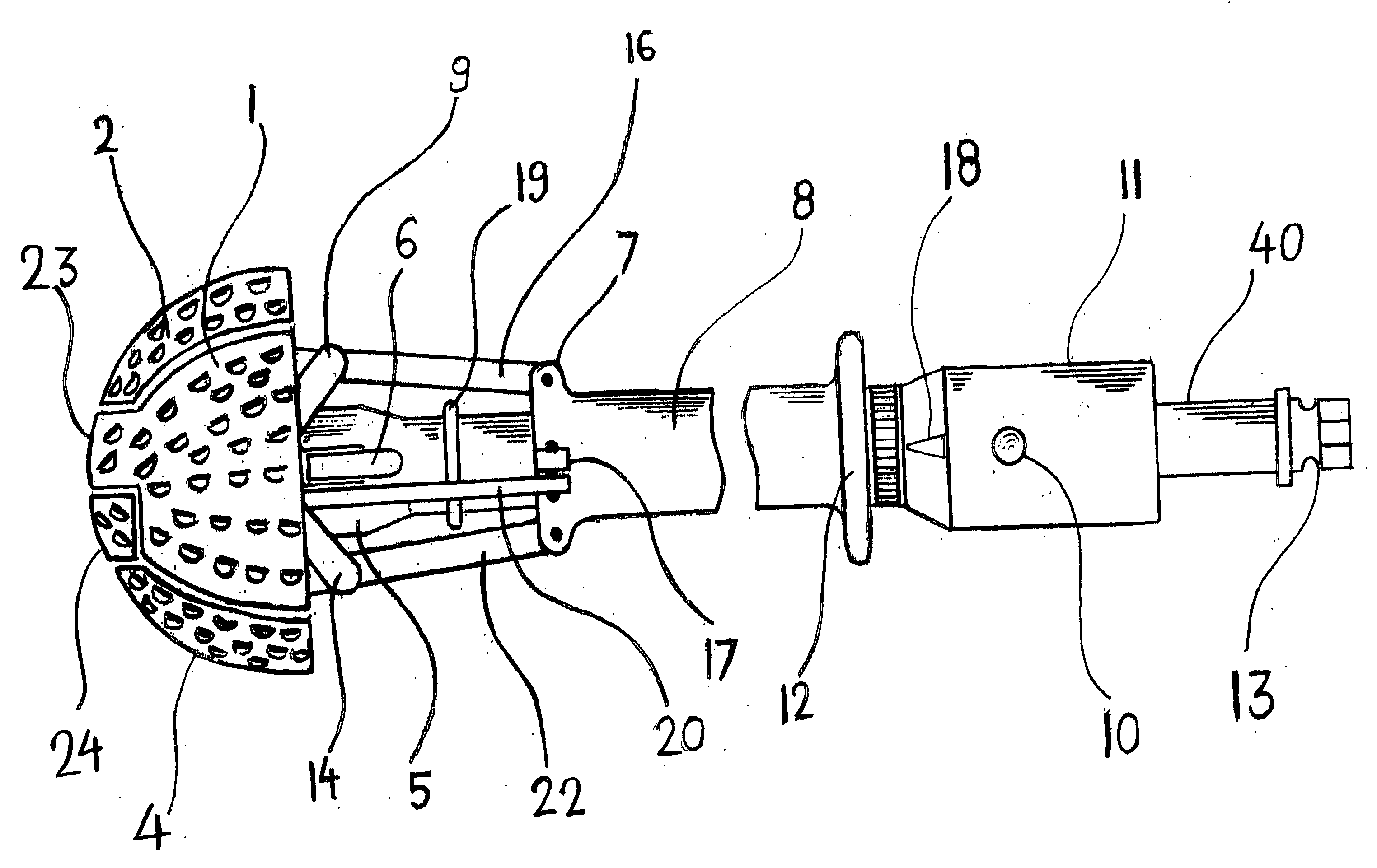
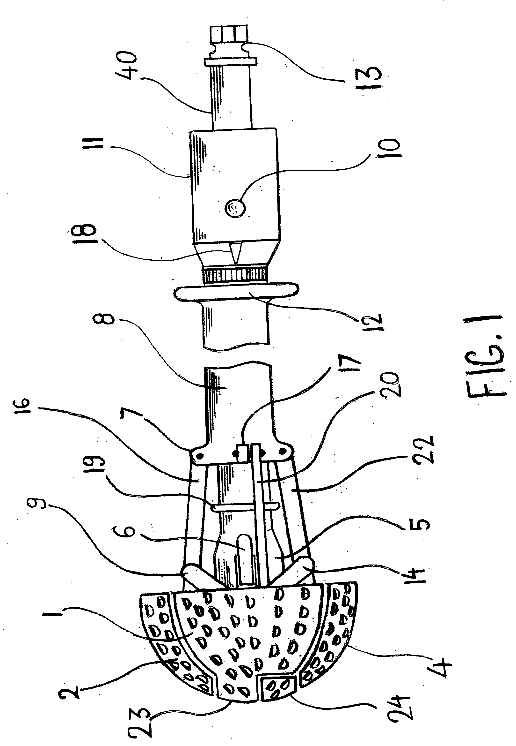
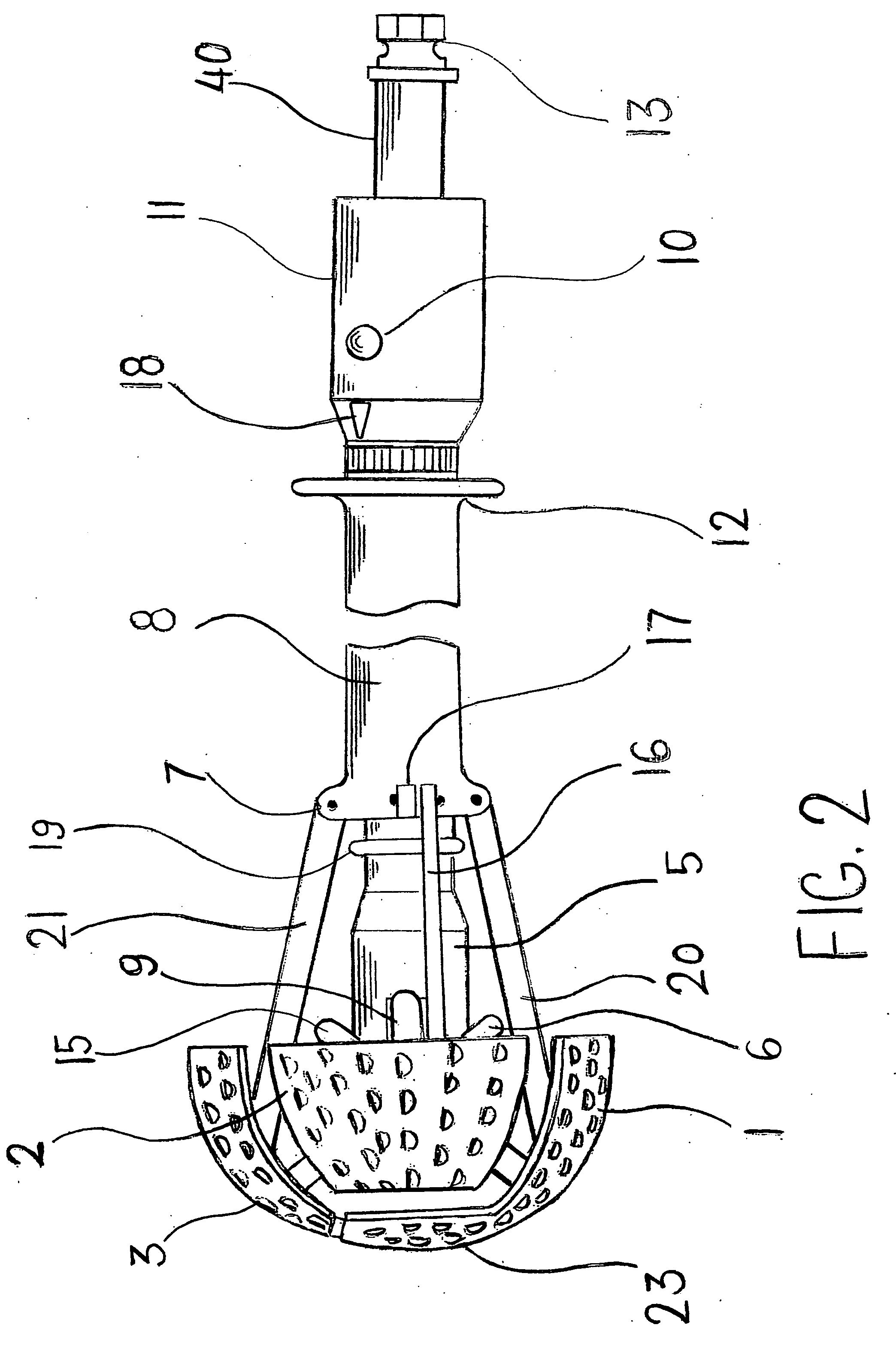
[0024] The expandable acetabular Reamer tool of this improved invention having opposed front and rear-ends 5 and 40 respectively. The front end 5 includes four arcuate and convex reaming segments as shown perspectively in FIGS. 1 and 2. The proximal end 40 is connectable to a surgical power drill known to the art by means of quick connect mechanism 13 as shown in FIG. 2 and FIG. 3.

[0025] Each of the four reaming segments 1, 2, 3, and 4 is solidly attached on the concave surface to a small shaft 6, 9, 14 and 15 (guiding shaft) situated in the center of the segment. Said shafts smoothly glide into four (two pairs) of tunnels 27, 29, 30 and 31 located in the distal end 5 of the reamer tool as shown in FIG. 8 and FIG. 9. The tunnels of each pair are coplanar and have openings diametrically opposed. In addition, each pair of tunnels is situated 90° angle to each other while maintaining a 45 degree angle with the longitudinal axis of the reamer tool. None of the tunnels communicate with ...


PUM


Abstract

In accordance with the present invention an improved spring-loaded expandable acetabular reamer is described, which comprises a number of convex reaming segments symmetrically located by pair around a central core of the Reamer tool. It is also an object of the present invention to provide and improved spring-loaded reaming segment, which expand faster and requires less manipulation by the operating surgeon and staff minimizing therefore the risk of infection and damage to tissue. Furthermore, introducing large size conventional acetabular reamers with rough and sharp edges through small surgical incisions will undoubtedly cause damage to the incision edge and the surrounding soft tissues, which may ultimately result in delayed wound healing. It is therefore highly desirable to provide an improved acetabular cup, which has the capacity of expanding in diameter to replace several acetabular cups thereby reducing the number of instruments used as well as shortening the time of the procedure and reducing healing time and lessen the risk of infection.

Description

BACKGROUND OF THE INVENTION [0001] 1. Field of Invention [0002] The present invention relates to new and improved expandable acetabular rotary reamer and more particularly to a method and apparatus used for total hip arthroplasty. [0003] 2. Prior Art [0004] Acetabular reamers are surgical tools, which are used during surgical procedures whereby artificial joints implants are inserted to replace articular surfaces damaged by disease. Traditionally, acetabular reamers have hemispherical surface, called reamer cup. Acetabular reamer cups are used to cut hemispherical surgical cavities in the pelvic bone. Said reamers have multiple cutting edges positioned over the spherical surface of the cup, which is attached to a tool driver. The later is driven in circular and rotation fashion by a power tool. The cutting edges would remove and grate damaged articular cartilage and continue reaming to remove a thin layer of the pelvic bone. The Reamer cup provides openings in a form of circular hol...

Claims


Application Information

Patent Timeline
Patent Type & Authority Applications(United States)
IPC IPC(8): A61B17/00
CPCA61B17/1617A61B17/1666
Inventor TERMANINI, ZAFER
Owner TERMANINI ZAFER
Why Eureka
Try Eureka