Method for correcting thermal displacement in a machine tool

a technology of thermal displacement and machine tool, applied in the direction of mechanical measuring arrangement, program control, instruments, etc., can solve the problems of difficult to set the standard temperature of cutting fluid, require higher running costs, and machining dimension errors, so as to achieve the effect of convenient setting operation

Active Publication Date: 2006-10-05
OKUMA CORP
View PDF4 Cites 33 Cited by
  • Summary
  • Abstract
  • Description
  • Claims
  • Application Information

AI Technical Summary

Benefits of technology

[0021] By setting the workpiece information such as the coordinate data of the fixed position of the workpiece, a coefficient of linear thermal expansion of the workpiece, and a standard temperature of the workpiece, it is possible to apply correction suitable for environment according to the fixed position of t

Problems solved by technology

This thermal displacement leads to dimension error of machining.
However, these methods require higher running cost and further have a problem that it is difficult to set a standard temperature of the cutting fluid.
However, when a relatively large workpiece such as a mold is cut, there is a problem that the thermal displacement of the workpiece varies depending on its fixed position on a table.
Moreover, in machining a relatively large workpiece such as a mold, when the wo

Method used


Image

  • Method for correcting thermal displacement in a machine tool
  • Method for correcting thermal displacement in a machine tool
  • Method for correcting thermal displacement in a machine tool

Examples


first embodiment

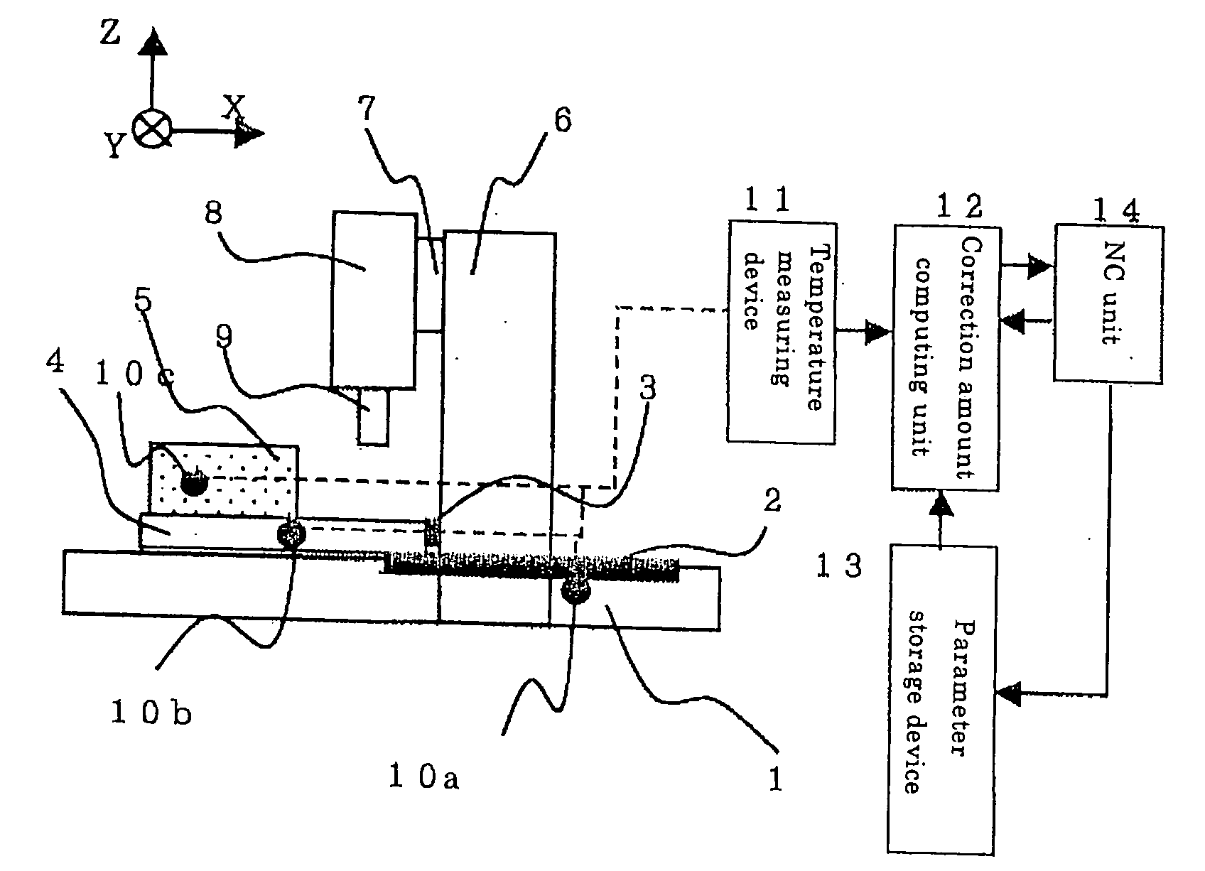
[0038] The first embodiment will be explained based on a flowchart of FIG. 6. At S1, a temperature measuring device 11 converts the analog signals into numerically expressed digital signals representing the temperatures of each sensor 10a-10c with a predetermined interval (10 seconds) by a well-known method. In a parameter storage device 13, the X-coordinates of the fixed position of the workpiece Xw, a coefficient of linear thermal expansion α, and a standard temperature are preset.

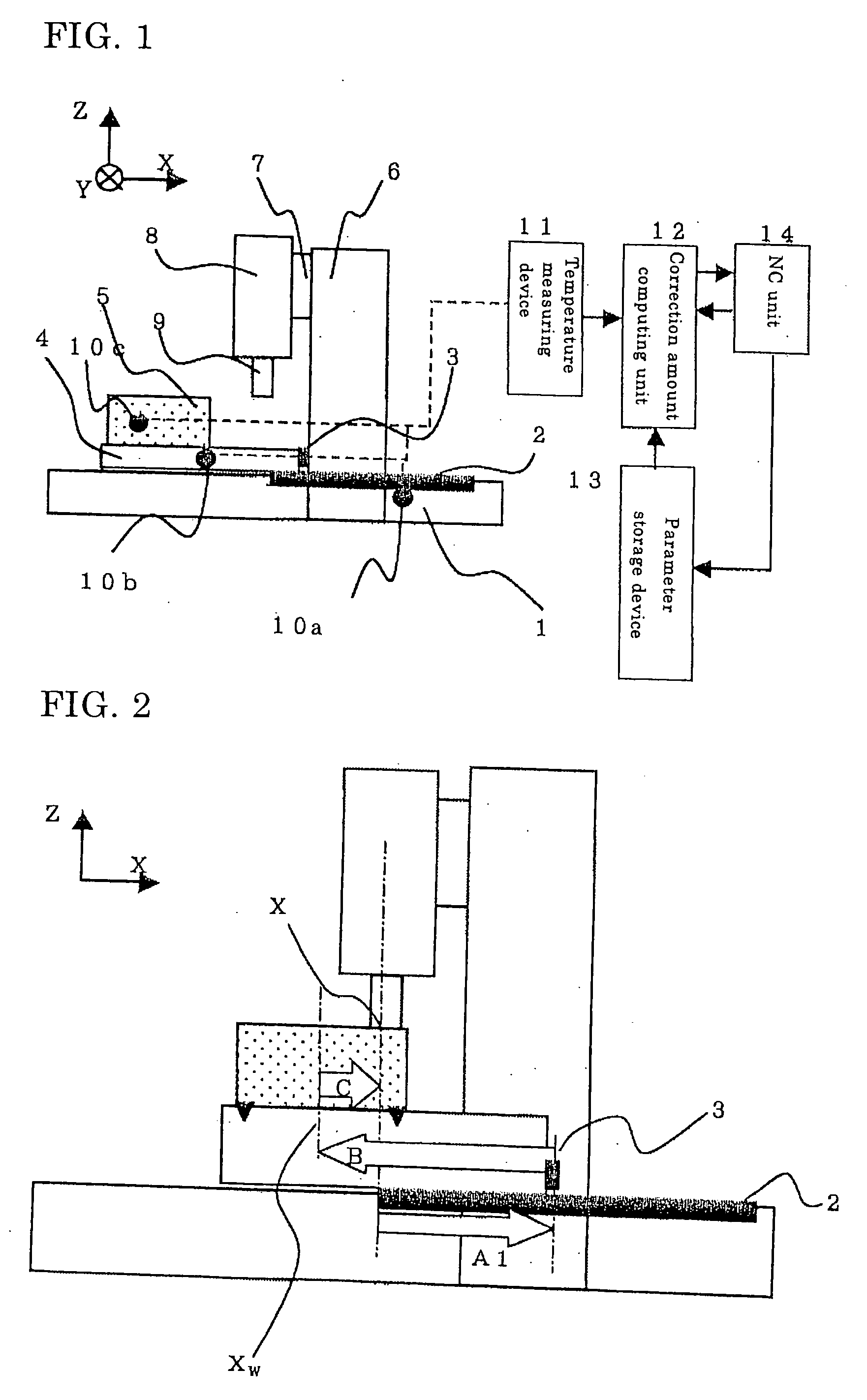
[0039] At S2, the X-coordinates of a current cutting edge position is detected by an NC unit 14. At S3, with a correction amount computing unit 12, an amount of displacement of the scale ΔA1, an amount of displacement of the table ΔB, and an amount of displacement of the workpiece ΔA2 are computed a using Equations 5, 6, and 7, respectively.

[0040] Here, as a computing method for obtaining a temperature for estimating the thermal displacement shown in the first term on the right-hand side of Equation 5,...

second embodiment

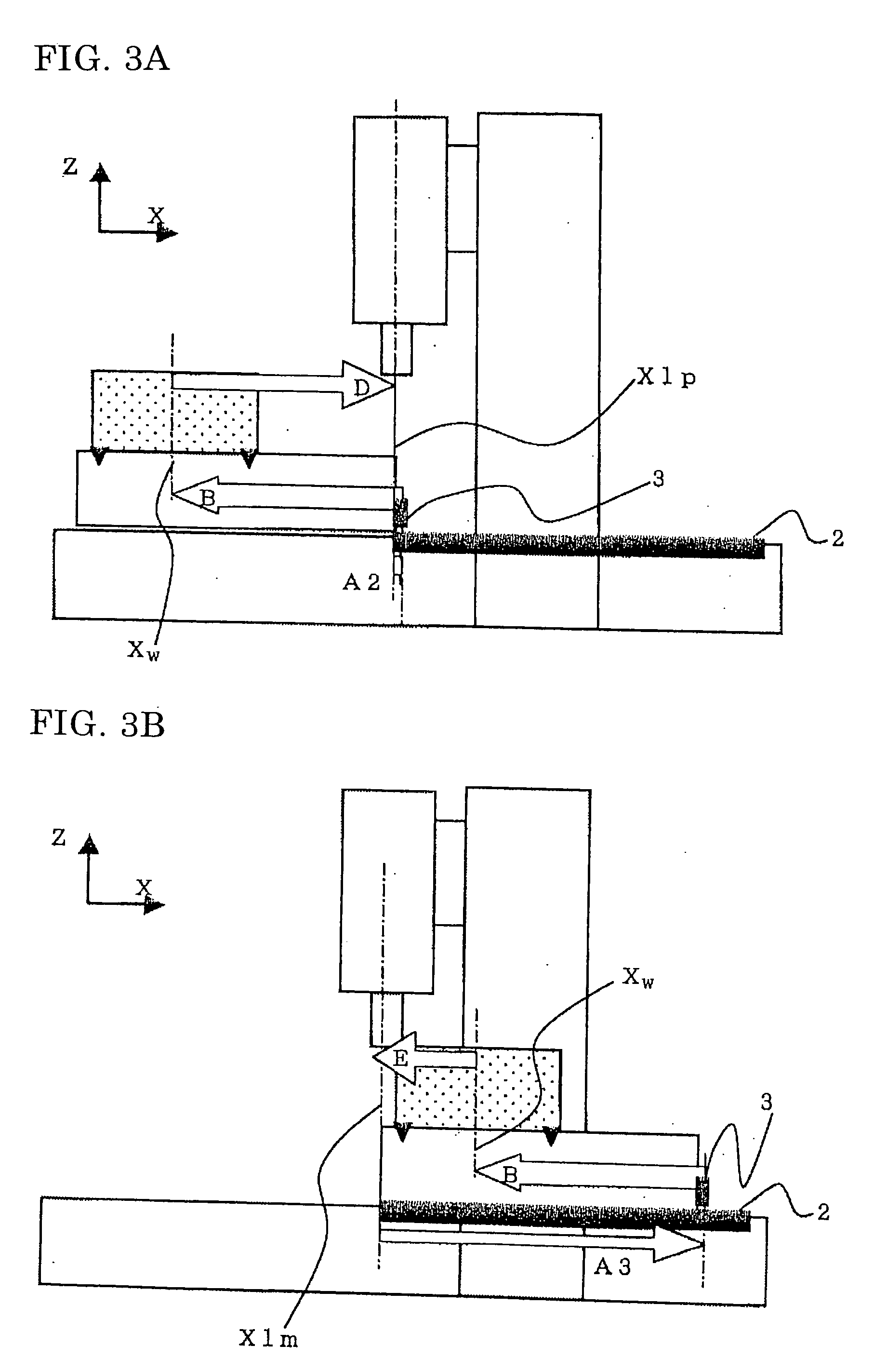
[0044] Another embodiment of the present invention will be explained based on a flowchart of FIG. 7. At S11, the temperature measuring device 11 converts the analog signals into numerically expressed digital signals representing the temperatures of each sensor 10a-10c with a predetermined interval (10 seconds) by a well-known method. In the parameter storage device, the X-coordinates of the positive end position of the cutting stroke Xlp, the X-coordinates of the negative end position of the cutting stroke Xlm, the X-coordinates of the fixed position of the workpiece Xw, and a standard temperature are preset.

[0045] At S12, with the correction amount computing unit 12, a correction amount XCP at the coordinate data of the positive end position of the cutting stroke is computed based on an amount of displacement of the scale ΔA2 (from Equation 9), an amount of displacement of the table ΔB (from Equation 6), an amount of displacement the workpiece ΔC2 (from Equation 12) using Equation...

third embodiment

[0049] Moreover, it is required that workpiece information, such as the coordinate data of the fixed position of the workpiece, a coefficient of linear thermal expansion of the workpiece, and a standard temperature (that requires dimensional accuracy of the workpiece) are set for each workpiece to be machined. For this reason, by providing a setting screen as shown in FIG. 4 to set the information with an operation panel, the setting operation becomes easy. Further, by setting the workpiece information using NC program, the workpiece information can be set in unattended machining process of the workpiece, for example, with an automatic pallet changer.


PUM


Abstract

A thermal displacement correction method includes the steps of: presetting the coordinate data of a fixed position of the workpiece on a table; finding an amount of displacement of the fixed position of the workpiece at a current cutting edge position based on the detected temperature, the coordinate data of the cutting edge position, and the coordinate data of the fixed position; computing the difference in the coordinate data between the fixed position of the workpiece and the cutting edge position; finding an amount of displacement of the workpiece between its fixed position and the cutting edge position based on the detected temperature and the difference in the coordinate data between the fixed position and the cutting edge position, and computing a sum of each amount of displacement to define an estimated value and correcting thermal displacement using an NC unit based on the estimated value.

Description

BACKGROUND OF THE INVENTION [0001] This application claims the benefit of Japanese Patent Application Number 2005-101479 filed on Mar. 31, 2005, the entirety of which is incorporated by reference. FIELD OF THE INVENTION [0002] The present invention relates to a method for correcting thermal displacement that varies depending on a position of a tool or a workpiece in a machine tool. DESCRIPTION OF THE RELATED ART [0003] In machining process of a machine tool, the machine tool and a workpiece are subject to thermal deformation due to change of environmental temperature of a room, heat emitted from the machine tool, and cutting heat. This thermal displacement leads to dimension error of machining. As a method to reduce the dimension error, from a mechanical or structural point of view, methods to keep a constant temperature of the machine and the workpiece have been proposed, for example, installation of the machine in a temperature-controlled room, and temperature control of cutting f...

Claims


Application Information

Patent Timeline
IPC IPC(8): G01B5/00
CPCG05B19/404G05B2219/49218G05B2219/49207G05B2219/49206
Inventor SATO, REIJI
Owner OKUMA CORP
Why Eureka
Try Eureka