Combined photoelectrochemical cell and capacitor

a photoelectrochemical cell and capacitor technology, applied in the direction of electrochemical generators, light radiation electric generators, greenhouse gas reduction, etc., can solve the problems of inconvenient, insufficient power supply line, and inability to have as many additional elements in the power supply line of wireless devices, and achieve the effect of reducing the number of components, increasing the complexity of the failure probability, and increasing the weight of each elemen

Inactive Publication Date: 2006-10-05
DYESOL IND
View PDF8 Cites 21 Cited by
  • Summary
  • Abstract
  • Description
  • Claims
  • Application Information

AI Technical Summary

Problems solved by technology

Power demand of a wireless product is typically non-uniform.
It is high for short periods of processing large amounts of data and low—for relatively long periods of standby state.
It is inconvenient, however, to have as many additional elements in power supply line of the wireless devices.
Each element adds to weight, complexity and failure probability.

Method used


Image

  • Combined photoelectrochemical cell and capacitor
  • Combined photoelectrochemical cell and capacitor
  • Combined photoelectrochemical cell and capacitor

Examples


Embodiment Construction

[0029] Having portrayed the nature of the present invention, a number of particular examples will now be described by way of illustration only. In the following description, reference will be made to the accompanying drawings in which:

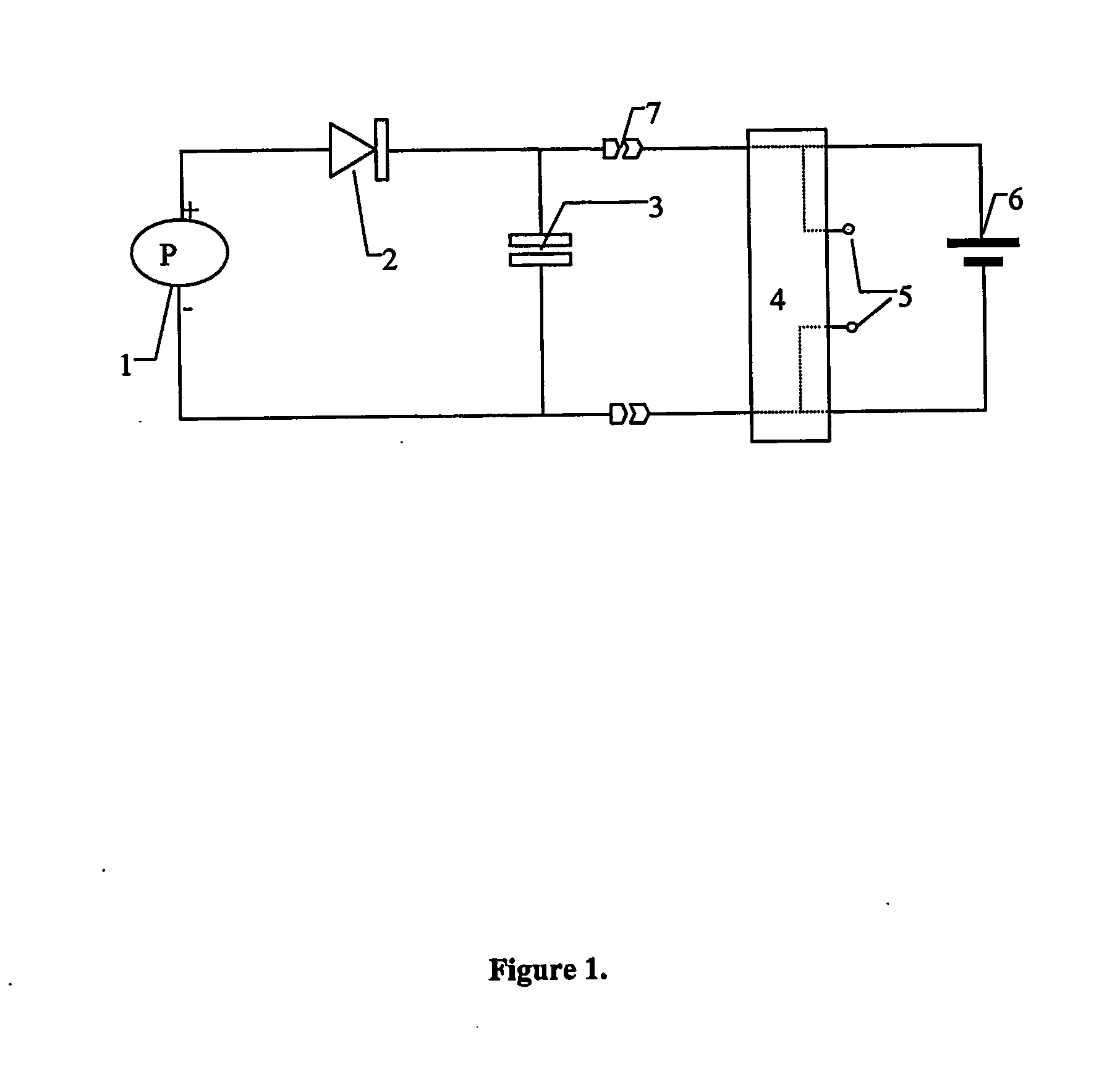
[0030]FIG. 1 presents equivalent electrical circuit elements of a combined PV and charge storage device connected to a battery, the device is to be illuminated from the working electrode side of the PV element. This device comprises the first example of the present invention.

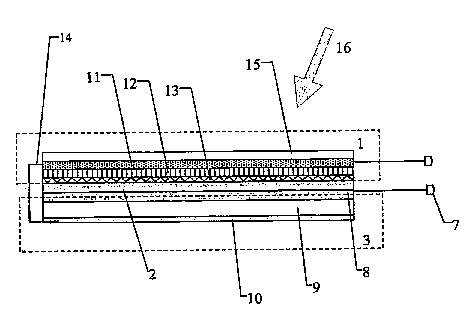
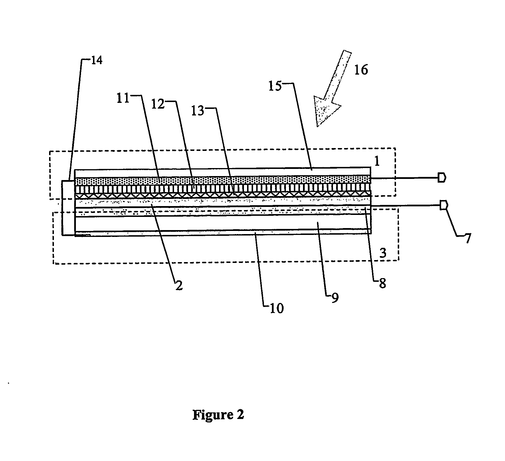
[0031]FIG. 2 is a diagrammatic cross-section illustrating the physical construction (not to scale) of a combined PV and charge storage device to be illuminated from the working electrode side of the PV element comprising the first example of the present invention.

[0032]FIG. 3 is the equivalent electrical circuit of a combined PV and charge storage device to be illuminated from the counter electrode side of the PV element comprising the second example of the present invention.

[0...


PUM

PropertyMeasurementUnit
areaaaaaaaaaaa
band gapaaaaaaaaaa
chargeaaaaaaaaaa

Abstract

A nanophotocapacitive device wherein: a photovoltaic element (1) extends over substantially the whole area of the device, a charge storage element (3) also extends over substantially the whole area of the device, connection mechanism (14) are provided for interconnecting the photovoltaic and charge storage elements, the photovoltaic element comprises a nanoparticulate dye sensitized layer (11) of wide band gap semiconductor, a catalytic layer (13) and an electrolyte (12) placed between the semiconductor and the catalytic layers. The photovoltaic (photoelectrochemical) element and charge storage element (capacitor) are formed on opposite sides of a titanium foil substrate (8). Light (16) is incident on the transparent electrode (15). A diode (2) may be integral with the device to prevent the charge storage element discharging when there is no solar energy input to the photovoltaic element.

Description

TECHNICAL FIELD [0001] This invention relates to combined electrical energy storage (ES) and photovoltaic (PV) devices and more particularly, but not exclusively, to such devices suitable for use as solar chargers / boosters for wireless electronic products (e.g. computer notebooks, sensors, mobile phones). BACKGROUND TO THE INVENTION [0002] The photovoltaic devices to which this invention is applicable will generally be used for wireless electronic applications. That is, they typically are connected to a rechargeable battery of a wireless product to maintain high charge state of the product. Power demand of a wireless product is typically non-uniform. It is high for short periods of processing large amounts of data and low—for relatively long periods of standby state. [0003] Prior art discloses examples of ES devices: batteries and capacitors. [0004] A photovoltaic (PV) cell can be used to supply additional energy to ES device. An additional diode element would be required to prevent...

Claims


Application Information

Patent Timeline
Patent Type & Authority Applications(United States)
IPC IPC(8): H02N6/00H01L31/00H01G9/20H01G9/26H01L31/058H01L51/00H01L51/30H01M14/00
CPCH01G9/2031H01G9/2068H02S40/38H01M14/005Y02E10/542H01L51/0086Y02E70/30H10K85/344
Inventor SKRYABIN, IGOR LVOVICHTULLOCH, SYLVIA MEDLYN
Owner DYESOL IND
Why Eureka
Try Eureka