
Cooling jacket

a technology of cooling jacket and cooling shell, which is applied in the direction of electrical equipment, lighting and heating equipment, instruments, etc., can solve the problems of not always being able to obtain sufficient cooling capacity, insufficient improvement, and inability to effectively transfer heat from the wall portions to the liquid coolant, etc., to achieve superior cooling capacity, reduce heat resistance, and improve heat transfer

Inactive Publication Date: 2006-10-05
HITACHI LTD
View PDF8 Cites 14 Cited by
  • Summary
  • Abstract
  • Description
  • Claims
  • Application Information

AI Technical Summary

Benefits of technology

The present invention provides a cooling jacket for reducing heat resistance and improving cooling capacity in electronic apparatuses. The cooling jacket includes a base portion with flow passages and a cover portion attached to the base portion. The base portion has a heat-transfer surface and a plural number of wall portions that define flow passages for the liquid coolant. The cover portion surrounds the base portion and defines a passage for guiding the coolant. The base portion is thermally isotropic to the heat-generating element to ensure efficient heat transfer. The technical effects of the invention include improved cooling efficiency, reduced heat resistance, and improved cooling capacity.

Problems solved by technology

However, it cannot be said necessarily that sufficient improvements are made, in relation to an improvement of the cooling jacket, in particular, the heat conduction thereof.
Thus, with the cooling jacket of the conventional art, the heat cannot be transferred effectively from the wall portions to the liquid coolant, even if enlarging the area to be contacted with the liquid coolant by means of the wall portions, and therefore it has a large heat resistance.
For this reason, there is pointed out a drawback that it is not always possible to obtain the sufficient cooling capacity with it.

Method used


Image

  • Cooling jacket
  • Cooling jacket
  • Cooling jacket

Examples


Embodiment Construction

[0017] Hereinafter, embodiments according to the present invention will be fully explained by referring to the attached drawings.

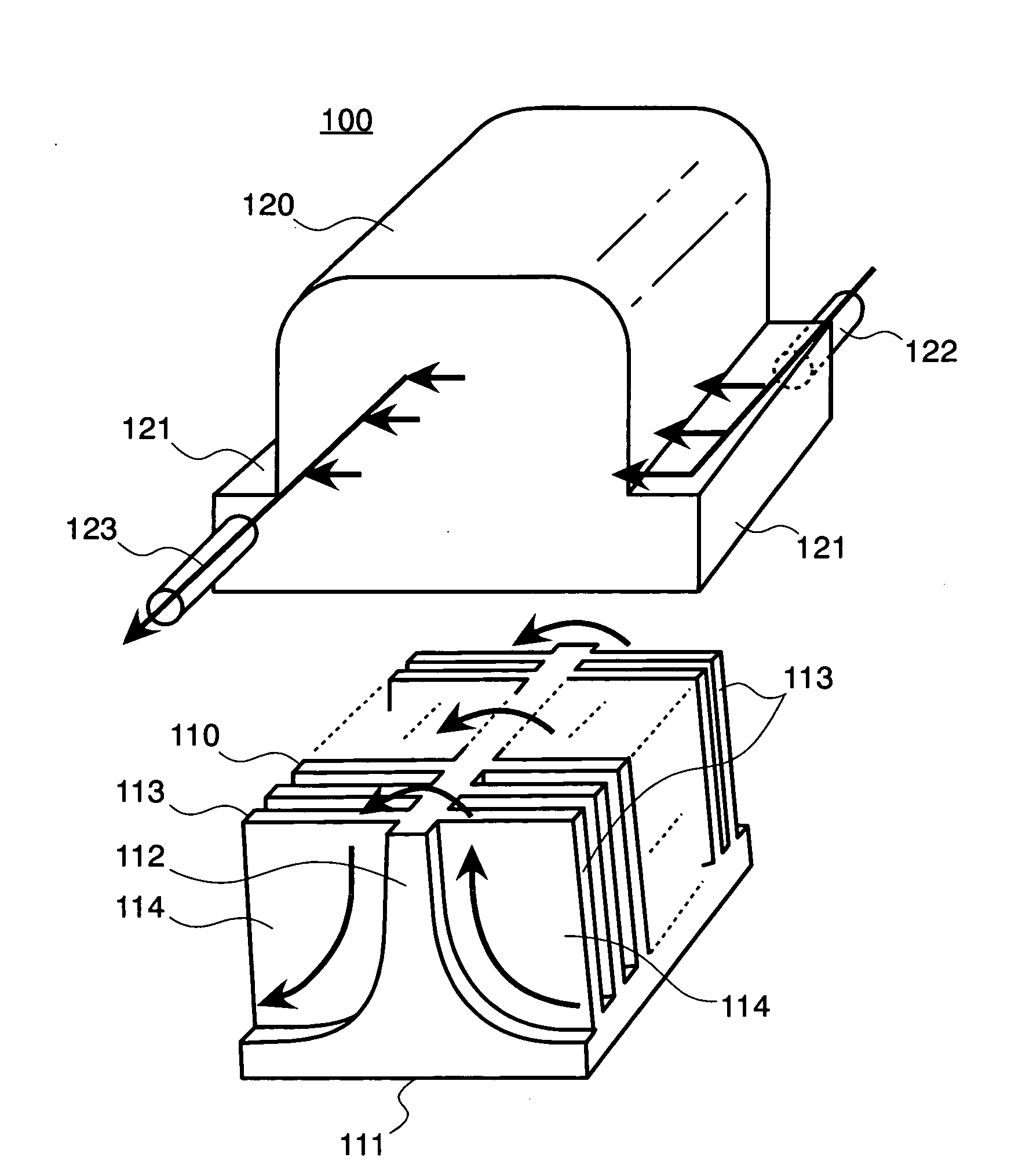
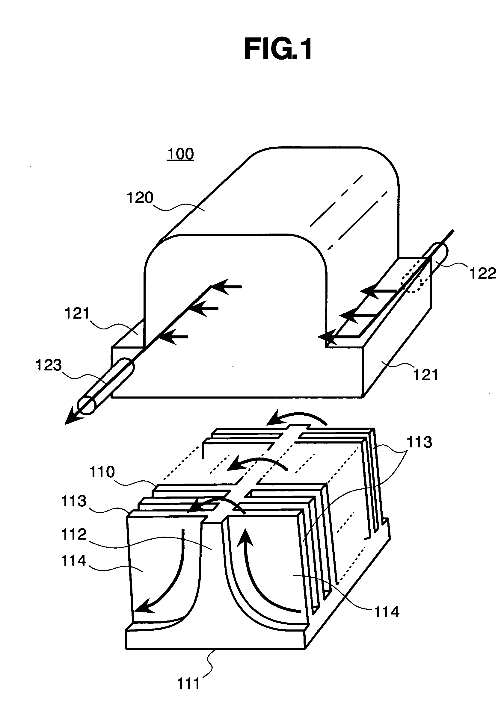
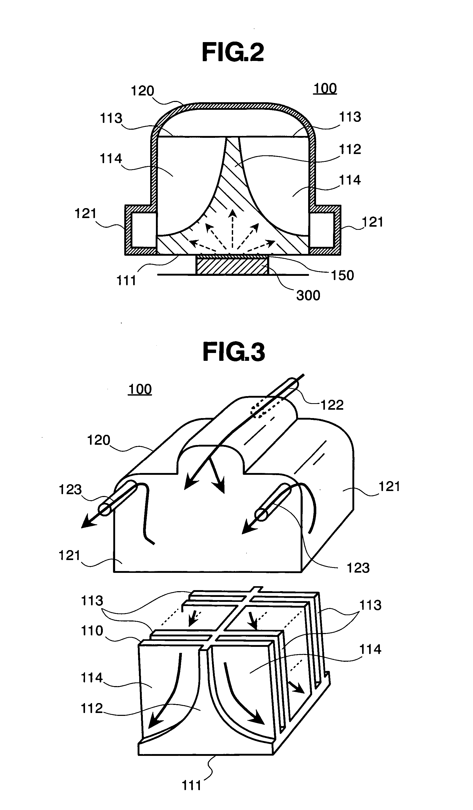
[0018] First of all, FIG. 1 attached herewith shows the structures of a cooling jacket, according to an embodiment of the present invention, through the exploded perspective view thereof. However, this cooling jacket builds up so-called a part of a liquid cooling system together with a radiator, a driving pump, and a tank, etc., though not shown herein, within an electronic apparatus including the heat-generating element (for example, the CPU, etc.) within an inside of a housing thereof, such as, the desk-top type personal computer and the server, and further the notebook-type personal computer, etc., for example. Further, those constituent parts are connected through metal tubes or the like, and an inside thereof is enclosed a liquid refrigerant or coolant, such as, water and / or ethylene glycol, for example.

[0019] The cooling jacket 100 according to the...


PUM


Abstract

A cooling jacket for cooling a heat-generating element 300 through transmitting heat-generation therein into a coolant flowing within an inside thereof, which is mounted within an electronic apparatus, comprises a base portion 110, having a heat-transfer surface 111 to be contact on a surface of the heat-generating element, and a plural number of wall portions 113, each being defined to extend into a direction perpendicular to the heat-transfer surface, thereby defining flow passages 114 for the liquid coolant between the wall portions; and a cover portion 120, being attached on the base portion surrounding a periphery thereof, thereby defining a passage for guiding the liquid coolant into the base portion, wherein the base portion builds up the sector-like shaped flow passages and a summit portion at a central portion of the base, and has a configuration being thermally isotropic to the heat-generating element to be contact thereon.

Description

BACKGROUND OF THE INVENTION [0001] The present invention relates to a cooling jacket for transmitting heat-generation into a liquid refrigerant or coolant flowing within an inside thereof, and in particular, it relates to a cooling jacket to be used within a liquid cooling system, for enabling effective cooling of a heat-generating element, within various kinds of electronic apparatuses mounting the said heat-generating element therein, i.e., a semiconductor integrated circuit element, within an inside thereof, such as, a desk-top type personal computer and a server, and further a notebook-type personal computer, etc. [0002] Conventionally, each of the electronic apparatuses, such as, the desk-top type personal computer and the server, and further the notebook-type personal computer, comprises the semiconductor element, as being the heat-generating element, such as, a CPU (Central Processing Unit), representatively, and for this reason, in general, it necessitates cooing for maintai...

Claims


Application Information

Patent Timeline
Patent Type & Authority Applications(United States)
IPC IPC(8): H05K7/20
CPCH01L23/3672H01L23/473H01L2924/0002H01L2924/00G06F1/20
Inventor ATARASHI, TAKAYUKINAKANISHI, MASATO
Owner HITACHI LTD
Learn More