
Rotary atomizer component

a technology of atomizer and component, which is applied in the direction of spraying apparatus, movable spraying apparatus, spraying nozzle, etc., can solve the problems of disturbing the splatter of cleaning fluid, the penetration of cleaning fluid during automatic cleaning,

Inactive Publication Date: 2006-10-05
DURR SYST INC
View PDF12 Cites 13 Cited by
  • Summary
  • Abstract
  • Description
  • Claims
  • Application Information

AI Technical Summary

Benefits of technology

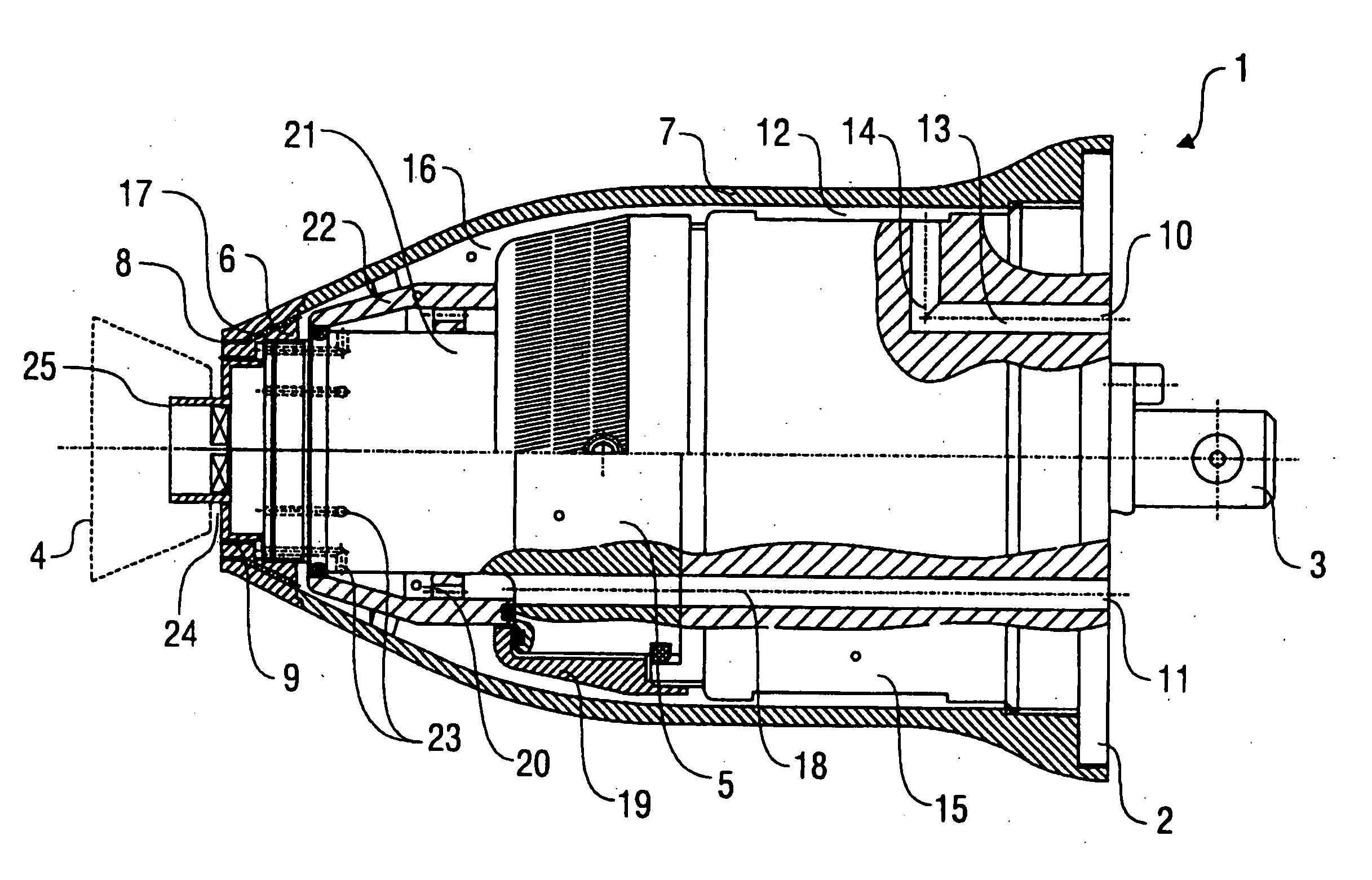
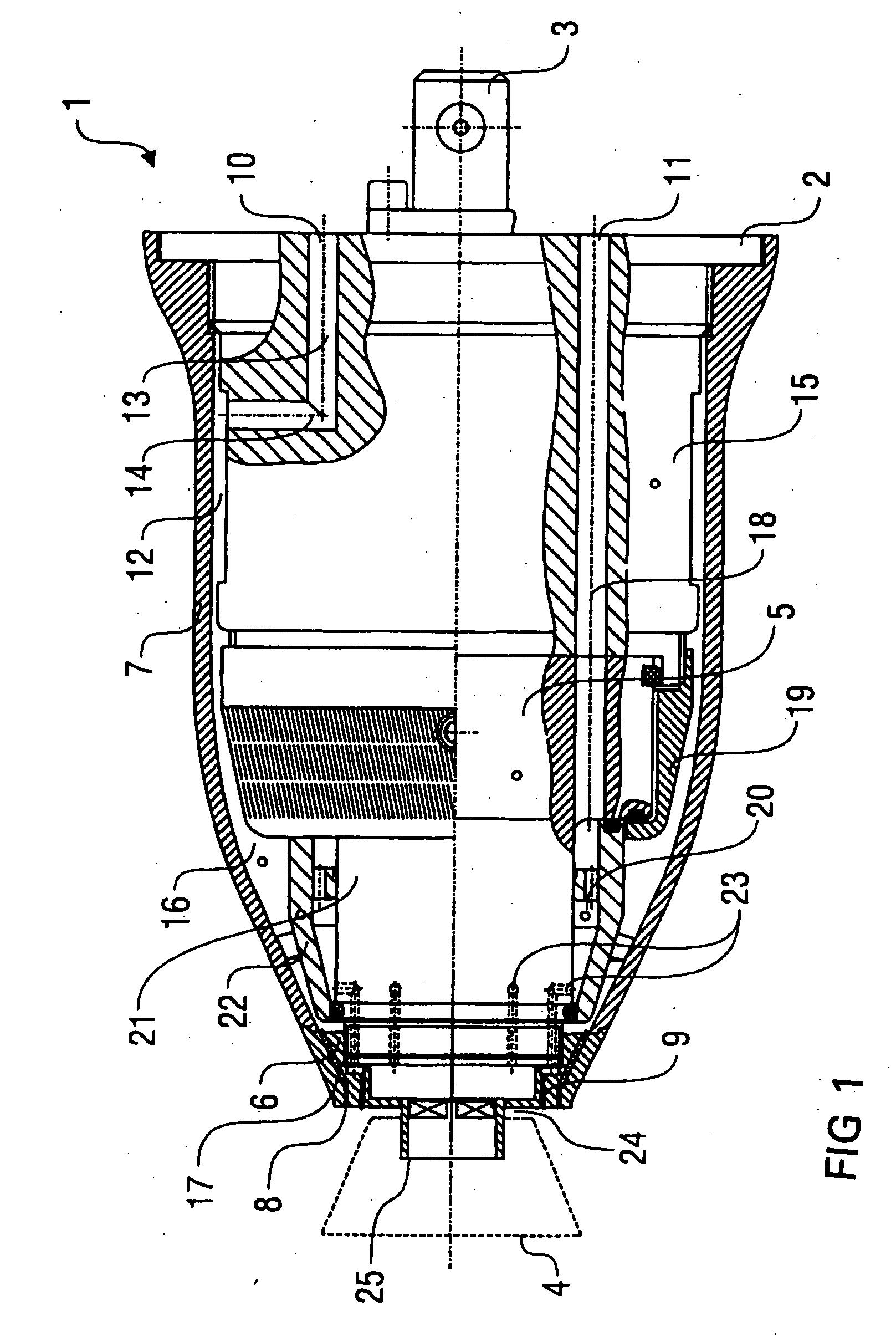
[0011] Therefore, the present invention lowers the vacuum in the ring slot between the bell cup and the air steering ring though adequate constructive measures, thereby counteracting penetration of coating material or cleaning fluid into the ring slot. One embodiment of the present invention provides a shaft cover in the shape of a bushing, which covers—at least partially—the bearing shaft in its mounted state in the area of the annular gap between the bell cup and the casing of the rotary atomizer. This shaft cover in the shape of a bushing prevents the penetration of cleaning fluid into the annular gap during automatic cleaning of the rotary atomizer. Preferably, the diameter of the shaft cover is between the exterior diameter of the bell cup and that of its shaft. Therefore, the invention must be told apart from those known rotary atomizers, in which rigid parts to fit cover partially the bell cup on its external side, so that no annular gap between the bell cup and the rotary atomizer is present at all.
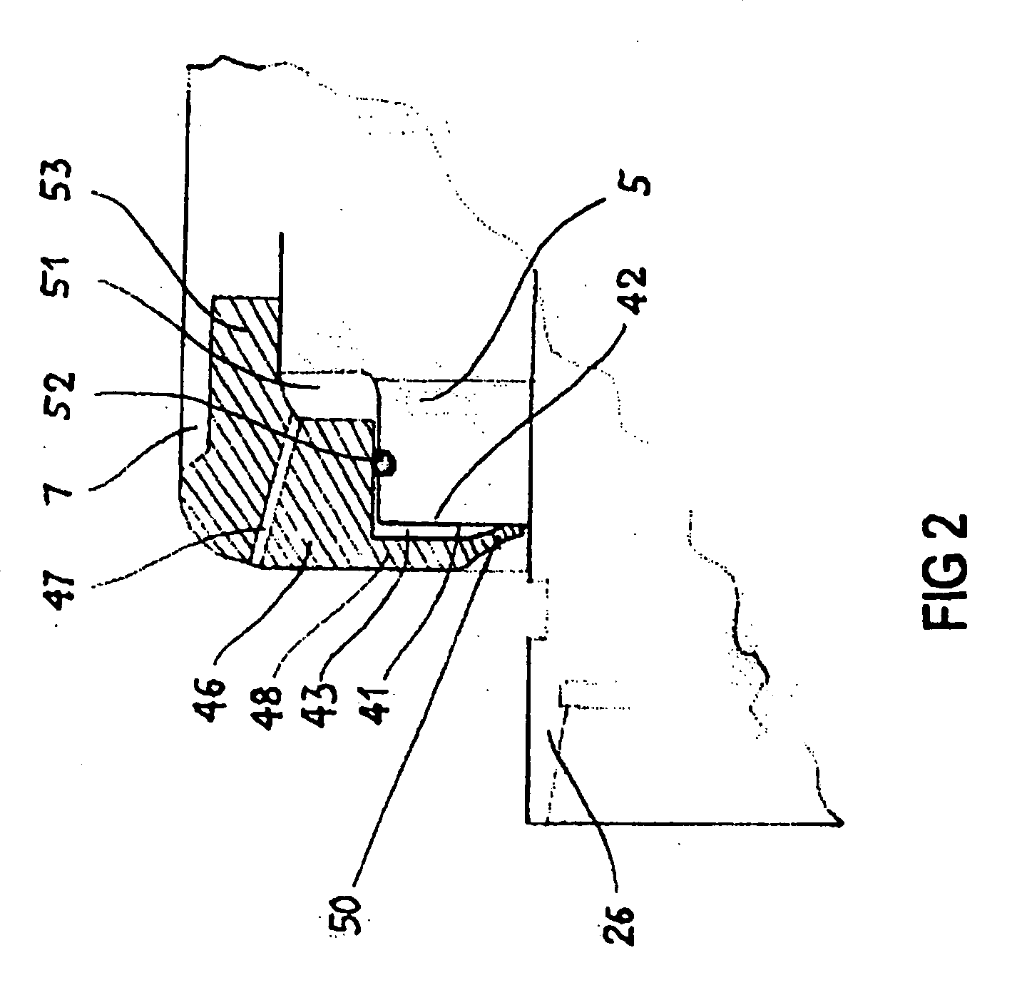
[0028] Accordingly, in yet another embodiment of the present invention, the rotary atomizer component is an air-steering ring forming the atomizer's front element. The sealing element forms a ring-shaped sealing lip can be located along its internal circumference thus forming the internal circumference or being located only in its proximity. This sealing element can be linked to an atomizer component such as the air-steering ring or any other front element, in one piece or in a way of being replaced. The capability replacing the sensitive sealing element can be practical in view of possible damages or wear and tear. The sealing element can consist of a sufficiently elastically deformable plastic material for its purpose, of which also consists the front element in the case of one piece, while in that of two pieces, the front element itself may consist of plastic or, for example, of metal. The sealing element my be integrated or, in a given case, fixed in a way so that it can be replaced, to any other part of the atomizer's casing instead of the air-steering ring or any front element. The sealing element may be also mounted onto the atomizer also as a completely separate component. In the case of an air-steering ring provided with a sealing element, the former be part of the rotary atomizer's casing as happens with properly known rotary atomizers. Instead of this it can also be formed as a separate component and possess, for example, an external thread by means of which it can be screwed onto an internal thread of the atomizer's casing or any other component of it.

Problems solved by technology

It is known that the air steering stream produces a vacuum in the circumferential annular gap between the bell cup and the air steering ring, which can lead to penetration of cleaning fluid during automatic cleaning, if the cleaning fluid is directed directly towards the unprotected annular gap between the bell cup and the air steering ring.
When cleaning the known rotary atomizer in an automatic cleaning system, this vacuum in the annular gap between bell cup and air steering ring can lead to cleaning fluid penetrating the annular gap remaining there even after the cleaning procedure, which can lead to disturbing splatters of cleaning fluid.

Method used


Image

  • Rotary atomizer component
  • Rotary atomizer component
  • Rotary atomizer component

Examples


Embodiment Construction

[0041] The rotary atomizer 1 shown in FIG. 1 shows on its mounting front area a mounting flange 2 with a mounting pivot 3 thus permitting mechanical mounting on a robot arm of a paint robot. Mounting of a rotary atomizer (such as rotary atomizer 1) on a robot arm is described in German Patent DE 43 06 800 A1, so that the contents of this publication can be accounted to the present description as to mounting rotary atomizer 1 on the robot arm to its fullest extent.

[0042] A conventional bell cup 4 can be mounted on the rotary atomizer 1, which, during operation of rotary atomizer 1, is powered via bearing shaft 26 supported by bearing unit 5 by a high-speed compressor turbine (not shown). Revolving the bell cup 4 leads in this case to accelerating the coating material injected into the interior of bell cup 4 axially and especially in a radial way, being sprayed on an edge of the bell cup.

[0043] The compressor turbine is powered by compressed air supplied from the paint robot over th...


PUM


Abstract

A rotary atomizer component, such as for a steering air ring or bell cup for a rotary atomizer with at least one steering air jet for delivering steering air (or controlled air) and a rotary bearing shaft where, in axial direction between the bell cup and the steering air jet, a circumferential annular gap is located. A shaft cover in form of a bushing covers the bearing shaft, when mounted, at least partially in the annular gap area between the bell cup and the steering air jet. In addition, the annular gap space between the front surface of the bearing unit and the internal surface facing it axially or any other front element of the atomizer is sealed in a radial way internally against the externally accessible area of the shaft. The sealing element provided for this purpose is located along the internal circumference of the air-steering rings or front element and able to be attached to the front surface of the bearing unit in a way that it is elastically deformable.

Description

TECHNICAL FIELD [0001] The present invention relates to a rotary atomizer component, such as for a steering air ring or bell cup for a rotary atomizer with at least one steering air jet for delivering steering air (or controlled air) and a rotary bearing shaft where, in axial direction between the bell cup and the steering air jet, a circumferential annular gap is located. A shaft cover in form of a bushing covers the bearing shaft, when mounted, at least partially in the annular gap area between the bell cup and the steering air jet. In addition, the annular gap space between the front surface of the bearing unit and the internal surface facing it axially or any other front element of the atomizer is sealed in a radial way internally against the externally accessible area of the shaft. The sealing element provided for this purpose is located along the internal circumference of the air-steering rings or front element and able to be attached to the front surface of the bearing unit i...

Claims


Application Information

Patent Timeline
IPC IPC(8): B05B1/28B05B1/32
CPCB05B3/1014B05B7/0815B05B3/1092B05B15/55
Inventor HERRE, FRANKSEIZ, BERNHARDBAUMANN, MICHAELNOLTE, HANS-JURGENMARQUARDT, PETER
Owner DURR SYST INC
Learn More