Beam irradiation device

a beam irradiation and beam technology, applied in the direction of conveyors, distance measurement, instruments, etc., can solve the problems of laser beam attenuation, measurement performance decline, measurement decline becomes a serious problem, etc., and achieve the effect of simple constitution

Inactive Publication Date: 2006-10-05
SANYO ELECTRIC CO LTD
View PDF9 Cites 10 Cited by
  • Summary
  • Abstract
  • Description
  • Claims
  • Application Information

AI Technical Summary

Benefits of technology

[0009] An object of the present invention is to provide a beam irradiation device capable of detecting nonuniformity of irradiation intensity of laser beams over a target region with a simple constitution. Further, the present invention also aims to provide a beam irradiation device capable of irradiating laser beams with a uniform light intensity over the target region based on the detection results.

Problems solved by technology

However, in a case where dirt, water droplets, and the like are attached to, or such as a flaw or a breakage occurs to this output window, power of the laser beams attenuates when passing through these potions of the output window.
As a result, measurement performance declines.
Such a decline in measurement becomes a serious problem when the beam irradiation device is for an in-vehicle application.
However, with this conventional technique, when the laser beams irradiated from a semiconductor laser are reflected on the dirt attached to the output window into the beam irradiation device, the reflected beams leak to a beam receiving portion for receiving reflected beams from the target region.
The leaked beams appear as noise in beam reception signals during a normal scan operation, and, as a result, cause such a problem of deterioration in accuracy in vehicle-to-vehicle distance detection and distance detection.

Method used


Image

  • Beam irradiation device
  • Beam irradiation device
  • Beam irradiation device

Examples


Embodiment Construction

[0043] Embodiments of the present invention will be described hereinafter with reference to the drawings.

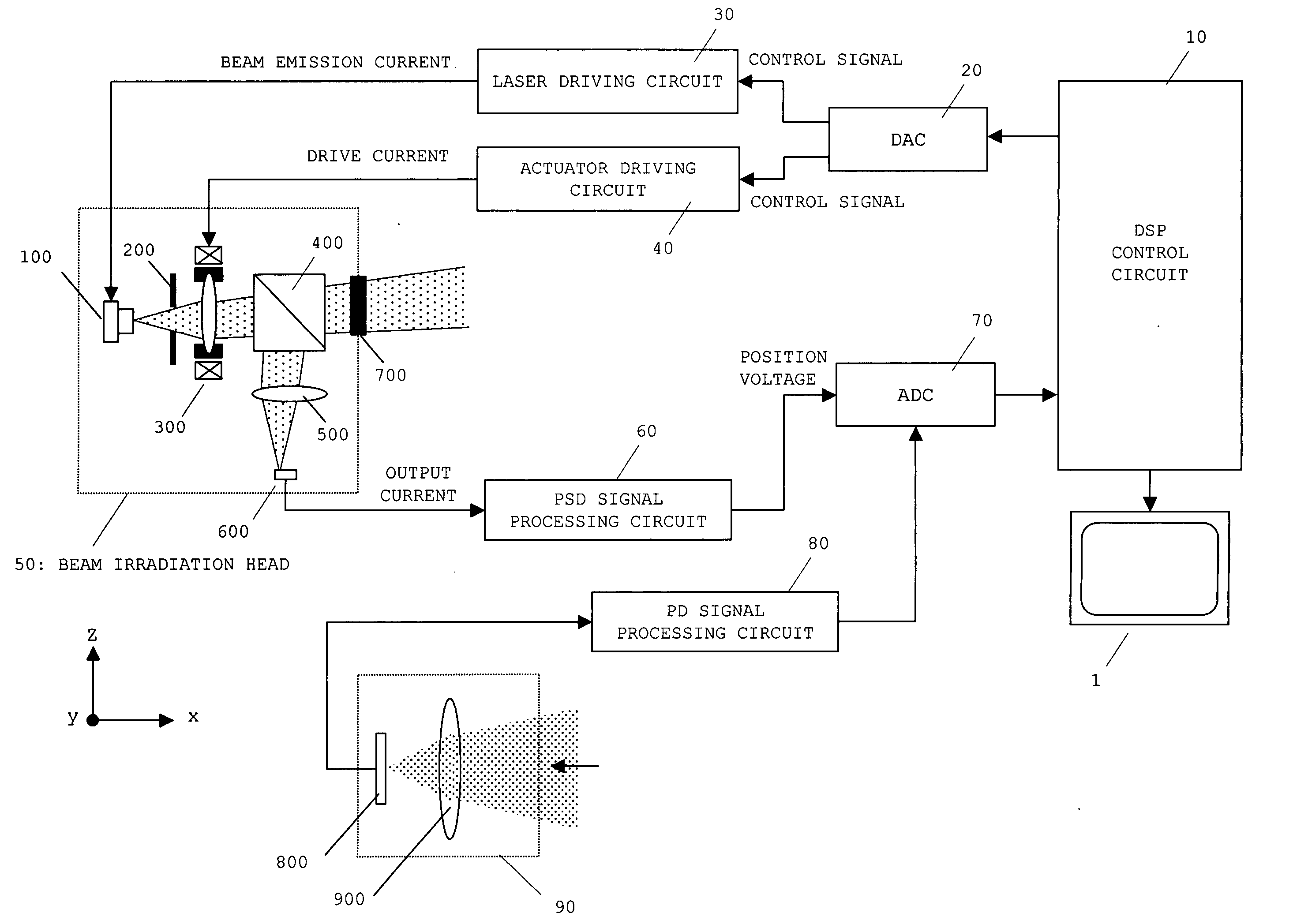
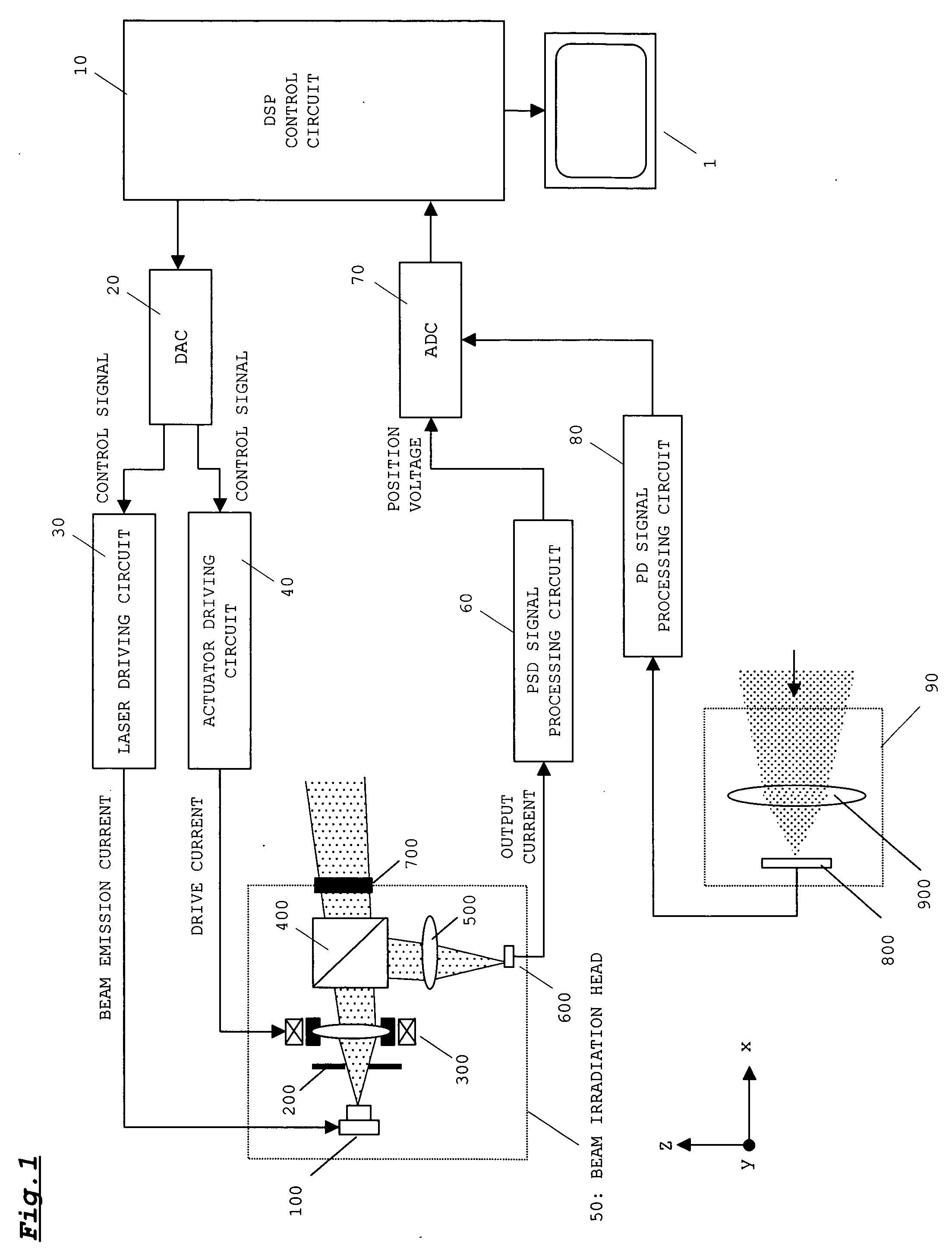
[0044]FIG. 1 shows the configuration of a beam irradiation device according to a first embodiment of the present invention.

[0045] As shown in FIG. 1, a beam irradiation device is provided with a digital signal processor (DSP) control circuit 10, a digital analog converter (DAC) 20, a laser driving circuit 30, an actuator driving circuit 40, abeam irradiation head 50, a position sensitive detector (PSD) signal processing circuit 60, an analog digital converter (ADC) 70, a photo detector (PD) signal processing circuit 80 and a beam receiving portion 90.

[0046] The DSP control circuit 10 outputs a digital signal for performing drive control of the laser driving circuit 30 and the actuator driving circuit 40 to the DAC 20. The DAC 20 converts the digital signal inputted from the DSP control circuit 10 into analog signals (control signals) and outputs the converted analog signals to...


PUM


Abstract

A DSP control circuit monitors a scan position of laser beams on the target region based on a signal from a PSD. Further, the DSP control circuit measures an amount of laser beams reflected from the target region for each scan position based on a signal from a beam receiving portion. The DSP control circuit compares an amount of reflected beams P0 at a scan position (reference position) on the target region with an amount of reflected beams Pk at a scan position adjacent to the scan position. If Pk/P0 is equal to or smaller than a threshold value Rs, it is determined that the scan position corresponding to the amount of reflected beams Pk is nonuniform in irradiation intensity of the laser beams. The DSP control circuit increases emission intensity plurality of times for the position that is determined to be nonuniform in irradiation intensity of the laser beams. With this, it is possible to make irradiation intensityies of the laser beams uniform over the target region.

Description

BACKGROUND OF THE INVENTION [0001] 1. Field of the Invention [0002] The present invention relates to a beam irradiation device suitably used for, for example, vehicle-to-vehicle distance detectors, distance detectors, and the like. [0003] 2. Description of the Related Art [0004] In recent years, vehicle-to-vehicle distance detectors and distance detectors using laser beams have been employed in various devices. A vehicle-to-vehicle distance detector, for example, detects the presence or absence of an obstacle and measures a distance to the obstacle by detecting reflected beams that are obtained when laser beams are radiated from a front portion of a vehicle. In this case, the laser beams are caused to longitudinally and laterally scan a target region preset in a front space. A time difference between timing for radiating the laser beams and timing for receiving the reflected beams is measured at each scan position, and a distance to an obstacle located in front of each scan position...

Claims


Application Information

Patent Timeline
Patent Type & Authority Applications(United States)
IPC IPC(8): G06M7/00
CPCG01S7/4811G01S7/4817G01S17/42G02B26/10G01S17/936G02B26/0875G01S17/48G01S17/931
Inventor YAMADA, MASATO
Owner SANYO ELECTRIC CO LTD
Why Eureka
Try Eureka