Eureka AIR delivers breakthrough ideas for toughest innovation challenges, trusted by R&D personnel around the world.

Photomultiplier

Active Publication Date: 2006-10-05
HAMAMATSU PHOTONICS KK
View PDF8 Cites 11 Cited by
  • Summary
  • Abstract
  • Description
  • Claims
  • Application Information

AI Technical Summary

Benefits of technology

[0013] In this way, in accordance with the photomultiplier, at least the accelerating electrode and dynode unit has a structure for holding unitedly in a state that at least the first-stage dynode and second-stage dynode included in the dynode unit is directly opposite to the accelerating electrode while they are not through a conductive member. As a result, a metal disk that is set to the same potential as that of a first-stage dynode, and that supports directly the first-stage dynode is not placed between the accelerating electrode and dynode unit; thus, variations of the transit time of the electrons may be drastically reduced in a route reached from the cathode to the second-stage dynode via the first-stage dynode.
[0015] The aforementioned united construction can be performed in such a manner that, for example, one or more protruding portions serving as a reference of the arranged positions of the focusing electrode and accelerating electrode, extending toward the photocathode, are provided for each of a pair of insulating support members for holding unitedly the plurality of dynodes included in the dynode unit. Namely, for each of the protruding portions, a first fixture structure for fixing the accelerating electrode in a state of supporting directly the accelerating electrode is provided, and a second fixture structure for fixing the focusing electrode in a state of supporting directly the focusing electrode is provided. In this case, in the photomultiplier, when the protruding portion (attached with the first and second fixture structures) serving as a reference of the arranged positions of the accelerating electrode and focusing electrode is provided for each of the pair of insulating support members for holding the dynode unit and anode, the focusing electrode, accelerating electrode, dynode unit, and anode constructing the electron-multiplying unit accommodated in the sealed container may be fixed unitedly to the pair of insulating support members. In other words, owing to the structure fixing the focusing electrode and accelerating electrode, provided at part of the pair of insulating support members for grasping unitedly the dynode unit and anode, the members constructing the electron-multiplying unit each can be simply positioned by using the pair of insulating support members as a reference member. As a result, on assembly of the electron-multiplying unit, positioning work with high precision between the members, specific fixing members and fixing jigs becomes unnecessary, which enables to improve drastically the productivity of the electron-multiplying unit accommodated in the sealed container. In addition, variations in performance between produced photomultipliers can be reduced irrespective of skilled degree of workers themselves.

Problems solved by technology

The inventors have studied the foregoing prior art in detail, and as a result, have found problems as follows.
In this case, there is a problem such that the effect of the metal disk arranged between the accelerating electrode and first-stage electrode occurs remarkable variations in the transit time of electrons reaching the second-stage dynode from the cathode via the first-stage dynode depending upon the emission area of photoelectrons of the cathode, thus increasing CTTD (Cathode Transit Time Difference) and deteriorating TTS (Transit Time Spread).

Method used


Image

  • Photomultiplier
  • Photomultiplier
  • Photomultiplier

Examples


first embodiment

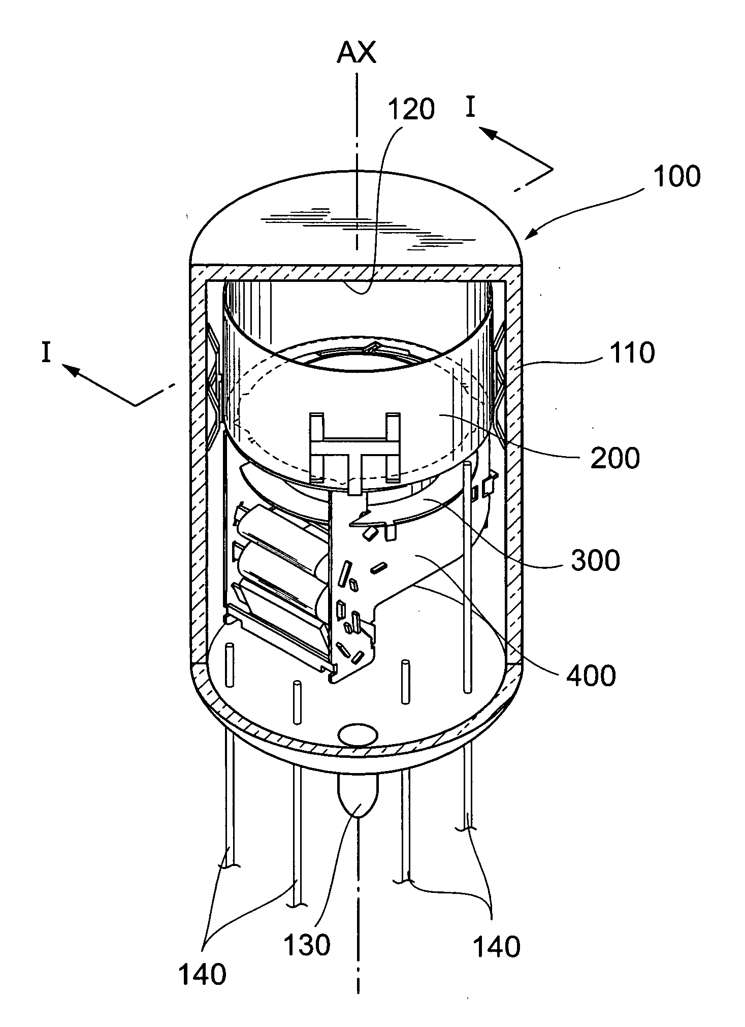
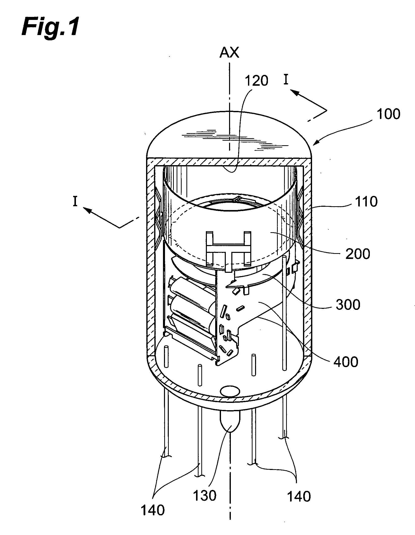
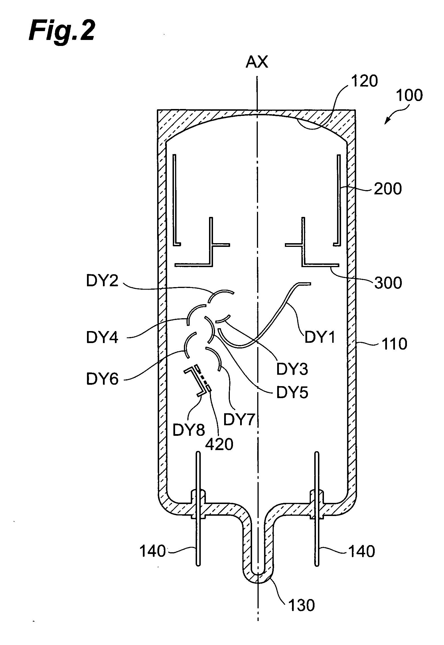
[0041]FIG. 2 is a view illustrating a cross-sectional structure of the photomultiplier taken along the line I-I depicted in FIG. 1.

[0042] In the photomultiplier 100 according to the first embodiment, the electron-multiplying unit 400 housed in the sealed container 110, as shown in FIG. 2, is unitedly held by a pair of insulating support members together with the focusing electrode 200 and accelerating electrode 300. In particular, associated with the accelerating electrode 300, the pair of insulating support members hold unitedly a first dynode (first-stage dynode) DY1 to a seventh dynode DY7, an anode 420, and a reflection-type of dynode DY8 for reversing the electrons passed through the anode 420 toward the anode 420 again.

[0043] Thus, in a state that at least the first dynode DY1 and second dynode DY2 contained in the dynode unit 400 is directly opposite to the accelerating electrode 300 without going through the conductive member, the photomultiplier 100 has a structure holdin...

second embodiment

[0072] For example, FIG. 14A is a view illustrating a sectional structure of the photomultiplier according to the present invention; FIG. 14B is a view illustrating a sectional structure of the application thereof.

[0073] In accordance with to the photomultiplier according to the second embodiment illustrated in FIG. 14A, similarly to a conventional photomultiplier, the first dynode DY1 contained in the dynode unit is supported directly between the accelerating electrode 300 and dynode unit, and a metal disk D2 set to the same potential as that of the first dynode DY1 is arranged therebetween. However, in the photomultiplier according to the second embodiment, the metal disk D2 has a through hole D2a to be passed through by the photoelectrons from the cathode 120; the shortest distance from the tube axis of the sealed container 110 to the edge of the through hole D2a is set to 1.3 times or more the shortest distance from the tube axis of the sealed container 110 to the end portion of...


PUM


Abstract

The present invention relates to a photomultiplier having a structure that enables to perform high gain and satisfy higher required characteristics. In the photomultiplier, an electron-multiplying unit accommodated in a sealed container comprises a focusing electrode, an accelerating electrode, a dynode unit, and an anode. Particularly, at least the accelerating electrode and dynode unit are held unitedly in a state that at least a first-stage dynode and a second-stage included in the dynode unit are opposite directly to the accelerating electrode not through a conductive material. A conventional metal disk for supporting directly dynodes which are set to the same potential as that of the first-stage dynode is not placed between the accelerating electrode and dynode unit; thus, variations of the transit time of electrons may be drastically reduced while the electrons reach from the cathode to the second-stage dynode via the first-stage dynode.

Description

CROSS-REFERENCE TO RELATED APPLICATION [0001] This application claims priority to Provisional Application filed on Mar. 31, 2005 by the same Applicant, which is hereby incorporated by reference in its entirety. BACKGROUND OF THE INVENTION [0002] 1. Field of the Invention [0003] The present invention relates to a photomultiplier that enables a cascade-multiplication of secondary electrons by emitting sequentially the secondary electrons through a plurality of stages in response to incidence of photoelectrons. [0004] 2. Related Background Art [0005] In recent years, developments of TOF-PET (Time-of-Flight-PET) are earnestly proceeding as a PET (Positron-Emission Tomography) apparatus for the next generation in the field of nuclear medicine. In particular, in the TOF-PET apparatus, when two gamma rays emitted from a radioactive isotope administered in a body are simultaneously measured at two detectors in directions opposite to each other, a time difference in signals outputted from th...

Claims


Application Information

Patent Timeline
IPC IPC(8): H01J43/04
CPCH01J43/06
Inventor OHMURA, TAKAYUKIKIMURA, SUENORIITO, MASUO
Owner HAMAMATSU PHOTONICS KK
Why Eureka
Eureka Blog
Learn More