Tag testing device, tag testing method, and tag testing program

a testing device and tag technology, applied in the direction of optical radiation measurement, fire alarms, instruments, etc., can solve the problems of defective tags, inability to identify the tag sheet location, and limited testing speed, so as to increase the testing speed of tags

Inactive Publication Date: 2006-10-05
FUJITSU LTD +1
View PDF11 Cites 24 Cited by
  • Summary
  • Abstract
  • Description
  • Claims
  • Application Information

AI Technical Summary

Benefits of technology

[0009] According to an aspect of the present invention, a tag testing device, a tag testing method, and a tag test...

Problems solved by technology

As a result, even with use of an anti-collusion function, a tag sheet location of a tag not functioning properly (hereinafter, “defective tag”) cannot be identified.
However, since the technology disclosed in U.S. Pat. No. 6,104,291 uses a testing method in which tags are tested one by one, the testing speed can only be increased to a l...

Method used


Image

  • Tag testing device, tag testing method, and tag testing program
  • Tag testing device, tag testing method, and tag testing program
  • Tag testing device, tag testing method, and tag testing program

Examples


Embodiment Construction

[0030] Reference will now be made in detail to the present embodiments of the present invention, examples of which are illustrated in the accompanying drawings, wherein like reference numerals refer to the like elements throughout. The embodiments are described below to explain the present invention by referring to the figures.

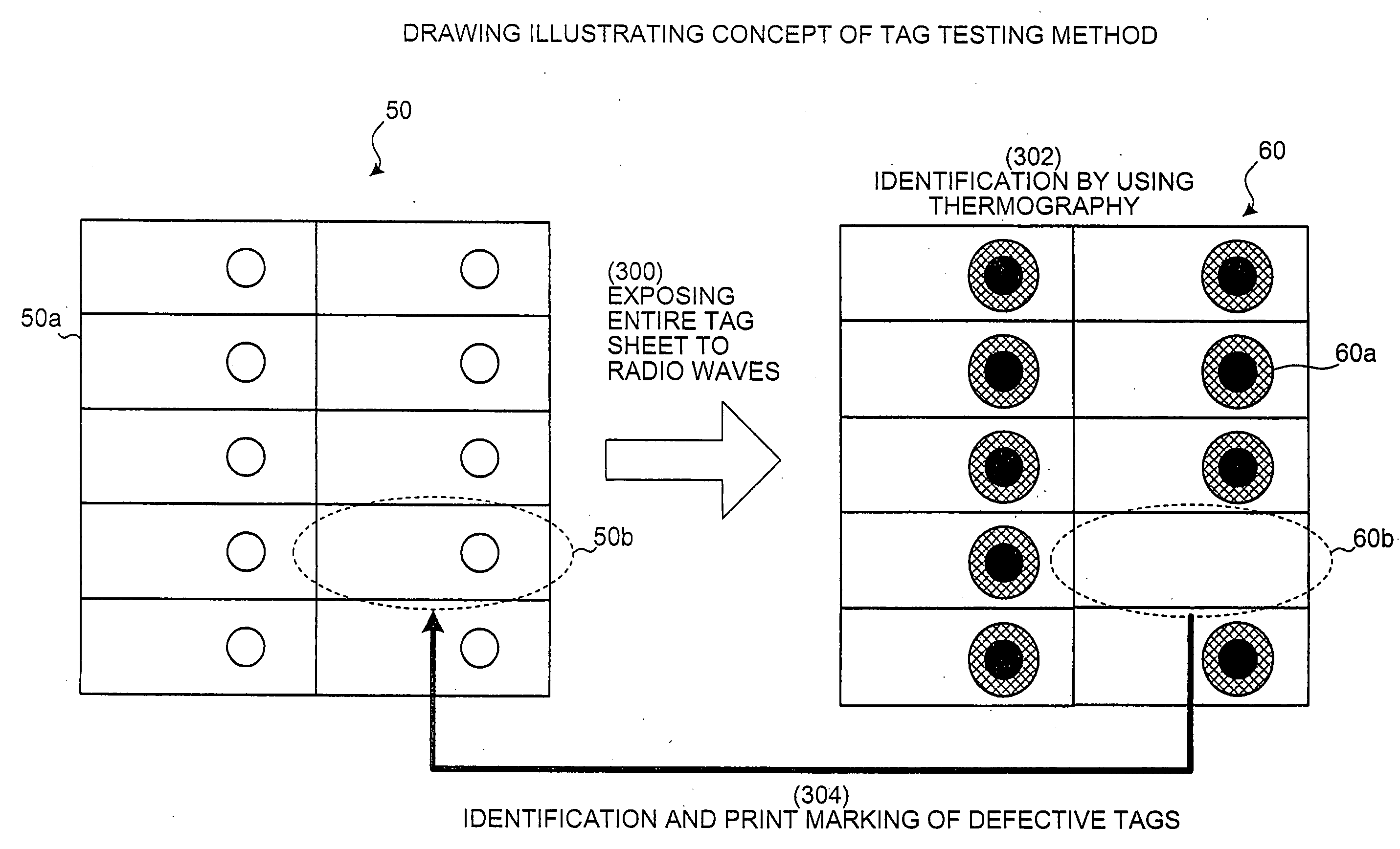
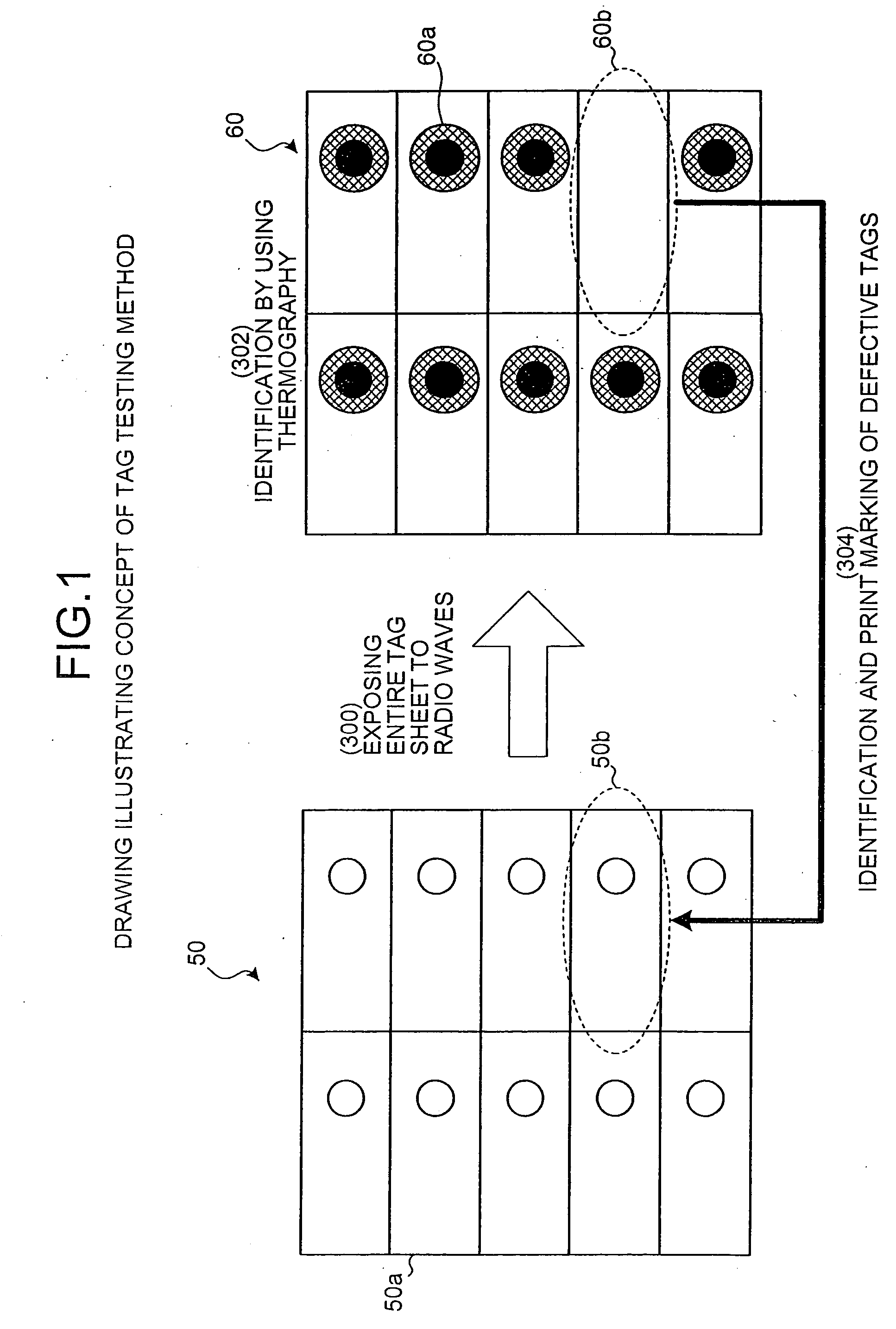
[0031] Radio waves or electromagnetic waves are bulk transmitted to non-contact Integrated Circuit (IC) tags (for example, radio frequency identification (RFID) tags) (hereinafter, simply referred to as “tags”), and the defective IC tags are detected based on whether the non-contact IC tags emit heat when radio waves or electromagnetic waves are transmitted to the non-contact IC tags. Because a large number of IC tags can be tested simultaneously by measuring simultaneously a heat emission status of each tag, tag testing speed can be increased and the tags can be tested while being attached to a tag sheet.

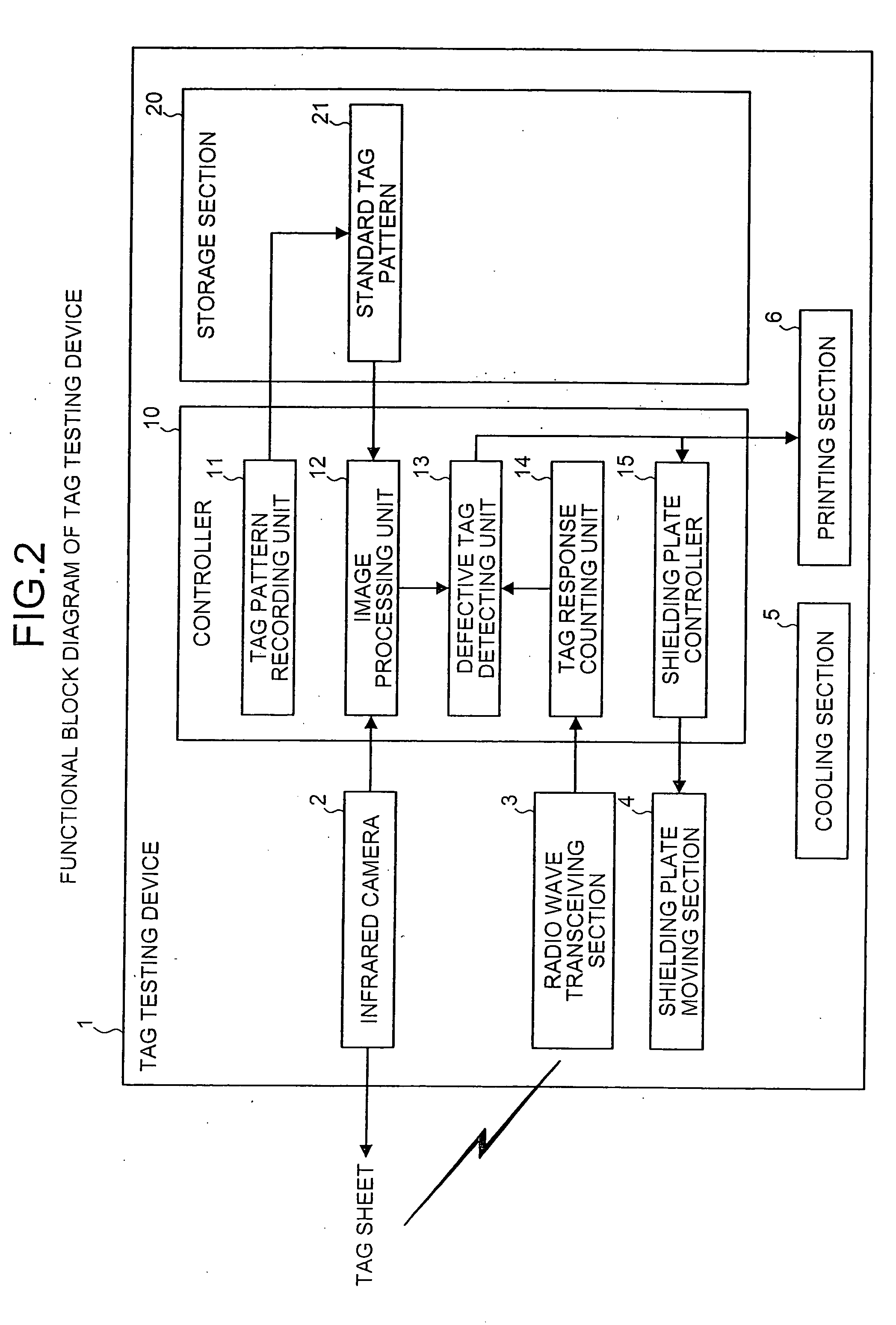
[0032] Further, a standard pattern representing a non...


PUM


Abstract

A tag testing device uses an infrared camera to take an image of a plurality of radio frequency identification tags, compares the image with a stored standard tag pattern image storage, and detects defective tags based on the comparison. A radio wave transceiver bulk reads the tags using anti-collision, a tag response counter counts a number of tag responses, and a defective tag detector compares a number of heat emitting tags based upon the image processing with a number of tag responses counted by the tag response counter. If the number of heat emitting tags does not match a number of responsive tags, a number of the tags tested are changed by partially shielding the tags and the radio wave transceiver repeatedly bulk reads the tags using the anti-collision function while a shielding range is gradually changed, thereby narrowing down other possible defective but heat emitting tags.

Description

CROSS-REFERENCE TO RELATED APPLICATIONS [0001] This application claims the benefit of Japanese Application No. 2005-094504, filed Mar. 29, 2005, in the Japan Patent Office, the disclosure of which is incorporated herein by reference. BACKGROUND OF THE INVENTION [0002] 1. Field of the Invention [0003] The present invention relates to a tag testing device, a tag testing method, and a tag testing program that detects a defective non-contact integrated circuit (IC) tag from a plurality of non-contact IC tags by exposing the non-contact IC tags to radio waves or electromagnetic waves. More particularly, the present invention relates to a tag testing device, a tag testing method, and a tag testing program that can increase the testing speed of the non-contact IC tags and can test the non-contact IC tags while being attached to a tag sheet. [0004] 2. Description of the Related Art [0005] Conventionally, in a manufacturing process of radio frequency identification (RFID) tags (hereinafter, ...

Claims


Application Information

Patent Timeline
IPC IPC(8): G08B13/14G01R31/26G06K17/00G06K19/07G06K19/077
CPCG01R31/311G01R31/2822G06K17/00
Inventor KAWAMATA, HIROSHI
Owner FUJITSU LTD
Why Eureka
Try Eureka