Rotating seal for anti-stiction of hydraulic struts

Inactive Publication Date: 2006-10-05
CRANE CO
View PDF17 Cites 14 Cited by
  • Summary
  • Abstract
  • Description
  • Claims
  • Application Information

AI Technical Summary

Benefits of technology

[0011] The method comprises rotating the seal between the piston and cylinder to reduce or eliminate the stiction. This method keeps strut movement to a minimum, thereby minimizing aircraft movement, and also minimizes temperature changes and pressure distortions caused by the temperature changes of the respective landing gear strut fluid. Rotating the seal overcomes the static friction on the seal and is replaced by the much smaller kinetic friction on the seal. While rotating the seal on each of the landing gear struts, the pressure within each of the landing gear struts is measured. This measurement may be compared to measurements of the pressure on the struts before and/or after the rotation of the seal. These pressure determinations are used to compensate for distortions caused by strut stiction.
[0012] In accordance with another aspect of the present invention, the stiction may be reduced by rotating the seals slightly to lubricate adjoining strut surfaces. This seal rotat

Problems solved by technology

The retention of the compressed nitrogen gas and hydraulic fluid by the O-ring seals is due to the extreme amount of friction these seals maintain as they move up and down the cylinder walls of the landing gear strut.
The Elfenbein prior art does not compensate for landing gear strut pressure distortions caused by strut stiction.
While these extreme up and down movements, raising and lowering the aircraft as much as 2-3 feet, may offer some relief to the potential errors in the prior art taught by Segerdahl, such extreme aircraft movement is incompatible wit

Method used


Image

  • Rotating seal for anti-stiction of hydraulic struts
  • Rotating seal for anti-stiction of hydraulic struts
  • Rotating seal for anti-stiction of hydraulic struts

Examples


Embodiment Construction

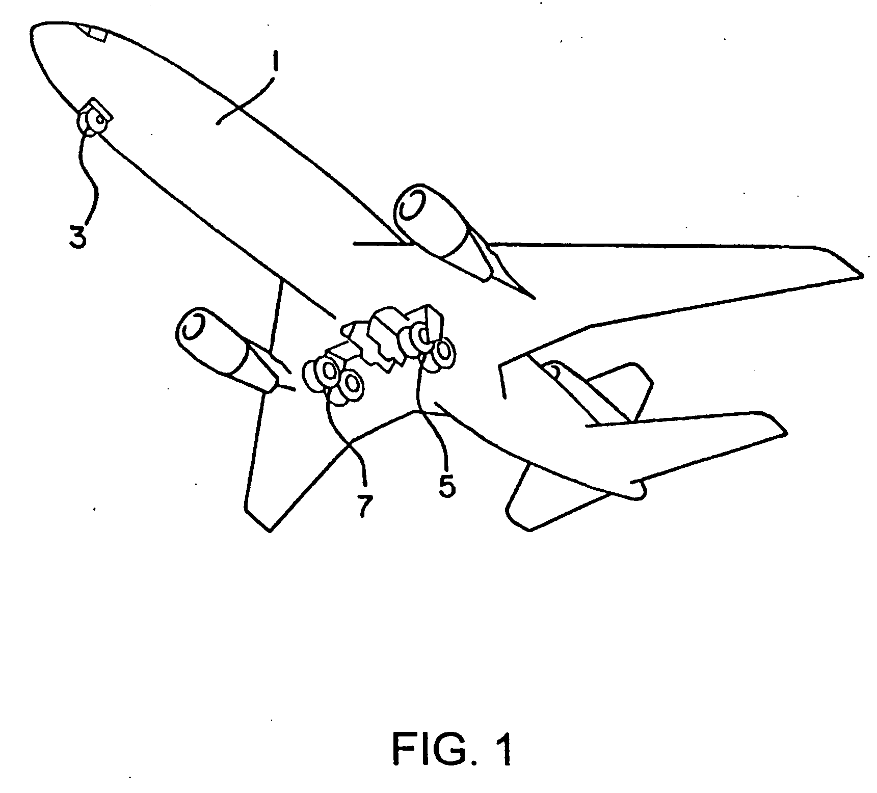
[0031] Referring now to the drawings, wherein like reference numerals designate corresponding parts throughout the several views and more particularly to FIG. 1 thereof, there is shown a typical commercial airliner 1 with tricycle landing gear configuration consisting of a nose landing gear 3, port main landing gear 5, and starboard main landing gear 7.

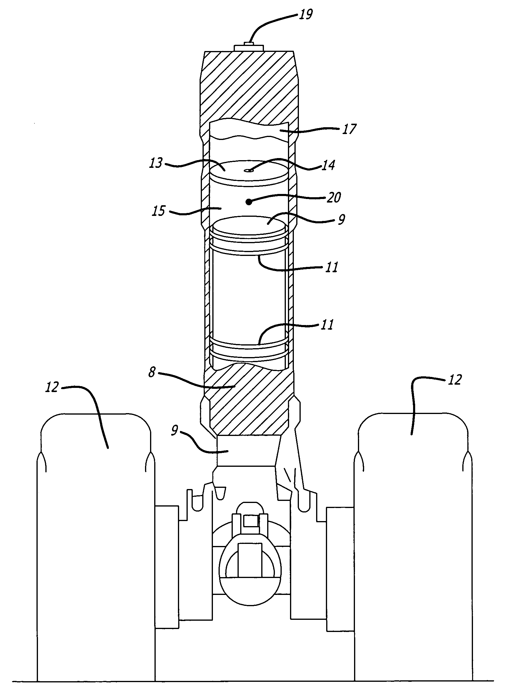
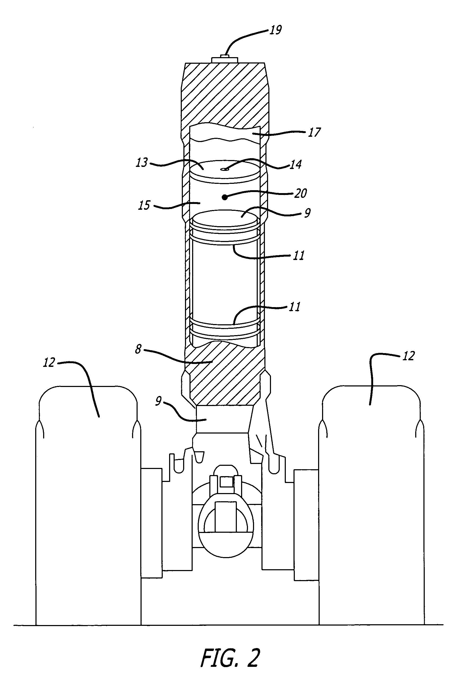
[0032] Referring now to FIG. 2, there is shown each conventional and commercially available landing gear 3, 5, 7 (FIG. 1) which consists of one oleo-type shock strut 8, hereafter referred to as “strut,” of which together support the weight of the airplane on tires 12, and an internal cushion of fluid, which also absorbs landing shock. In commercially available struts 8 the fluid includes hydraulic liquid (referred to herein as hydraulic fluid 15) and nitrogen gas 17. Internally each strut contains a forged steel piston 9, with an orifice plate 13 containing an orifice hole 14 that dampens the strut compression motion. O-ring seals 11...


PUM


Abstract

An onboard system for use in measuring, computing and displaying the weight and center-of-gravity for aircraft, while keeping aircraft movement to a minimum. Pressure sensors are mounted in relation to each of the landing gear struts. A motor and rotating seal are configured into each strut and are activated by a computer/controller, while landing gear strut pressures are monitored in the determination of strut stiction. The computer/controller calculates the stiction of each landing gear strut and compensates for the pressure distortions caused by landing gear strut stiction. Additional features include reducing strut stiction, measuring landing gear strut fluid levels, monitoring landing gear strut health, weight adjustments for external ice and de-icing fluids, weight adjustments for wind, monitoring aircraft landing gear strut movement.

Description

CROSS-REFERENCES TO RELATED APPLICATIONS [0001] This application is based upon provisional application Ser. No. 60 / 667,723 filed on Mar. 30, 2005.FIELD OF THE INVENTION [0002] This invention is related to determining the load on aircraft struts. BACKGROUND OF THE INVENTION [0003] Two critical factors in the flight of any aircraft are the weight and balance of that aircraft. This is to insure that at take-off speed, the wings are generating sufficient lift to lift the weight of the airplane. An equally important factor to consider is whether the airplane is in proper balance (center of gravity) or within acceptable limits, as can be compensated for by trim adjustments. [0004] The weight of an aircraft is supported on a plurality of collapsible landing gear struts. These landing gear struts contain pressurized hydraulic fluid and nitrogen gas. The pressure within each landing gear strut is related to the amount of weight that landing gear strut is supporting. Multiple O-ring seals wit...

Claims


Application Information

Patent Timeline
IPC IPC(8): G08B21/00B64C25/00
CPCB64C25/00G01G19/07B64F5/0045B64C25/60B64F5/60
Inventor STOCKWELL, DANIELGONIODSKY, IGAL
Owner CRANE CO
Why Eureka
Try Eureka