
Optical compensation sheet, polarizing plate and liquid crystal display

a liquid crystal display and polarizing plate technology, applied in the direction of optical elements, instruments, transportation and packaging, etc., can solve the problems of slow display response, limitation of the range of retardation control, and art is insufficient to produce an effect of reducing viewing angle dependen

Active Publication Date: 2006-10-05
FUJIFILM CORP
View PDF1 Cites 15 Cited by
  • Summary
  • Abstract
  • Description
  • Claims
  • Application Information

AI Technical Summary

Benefits of technology

[0007] An object of an illustrative, non-limiting embodiment of the invention is to provide an optical compensation sheet, which can ensure high-quality images with a slight change in hue of display color when the screen is viewed from oblique directions. Another object of an illustrative non-limiting embodiment of the invention is to provide a polarizing plate and a liquid crystal display, which each have such an optical compensation sheet.
[0009] And it has also been found that optical compensation members as specified below can realize ideal wavelength dispersion characteristics of retardation and ensure slight viewing-angle dependences of hue and black display when used in liquid crystal displays, thereby achieving the invention.
[0011] In accordance with the invention, it becomes possible to provide an optical compensation sheet capable of ensuring high-quality images with a slight change in hue of display color when viewed from oblique directions, and a polarizing plate and a liquid crystal display which each have such an optical compensation sheet.

Problems solved by technology

Liquid crystal displays are expanding the range of their uses year after year because of their low power consumption and high space-saving rate as image display devices.
Although great viewing-angle dependence of images and slow display response were major drawbacks to liquid crystal displays in the past, fast-response VA mode liquid crystal display models with wide viewing angles have recently been commercialized, and thereby the demand for liquid crystal displays is rapidly growing even in the market requiring high-quality images, such as the TV-set market.
However, such an art is insufficient to produce an effect of reducing viewing-angle dependence of hue, so improvements in this point have been required.
However, such methods pose limitations to the range of retardation control and are insufficient in point of hue changes by viewing angles.

Method used


Image

  • Optical compensation sheet, polarizing plate and liquid crystal display
  • Optical compensation sheet, polarizing plate and liquid crystal display
  • Optical compensation sheet, polarizing plate and liquid crystal display

Examples


example 1

[0237] In a reaction vessel equipped with a refluxing device, 100 parts by mass of cellulose (hardwood pulp) and 160 parts by mass of acetic acid were placed, and stirred for 2 hours at an inside temperature of 40° C. The thus pretreated cellulose took on the shapes of from fine powder to feathers by being swollen, broken and crushed.

[0238] Aside from the pretreatment, a mixture of 920 parts by mass of butyric anhydride and 10 parts by mass of sulfuric acid was prepared as an acylation agent, cooled to −20° C., and then added to the reaction vessel in which the pretreated cellulose was stored. After a lapse of 30 minutes, the temperature inside the reaction vessel was raised to 20° C. and the cellulose underwent reaction with the acylation agent for 5 hours. Thereafter, the temperature inside the reaction vessel was cooled to 5° C., and thereto 2,400 parts by mass of a 12.5 mass % of aqueous acetic acid solution cooled at about 5° C. was added over a period of one hour. Then, the i...


PUM

PropertyMeasurementUnit
Fractionaaaaaaaaaa
Fractionaaaaaaaaaa
Fractionaaaaaaaaaa

Abstract

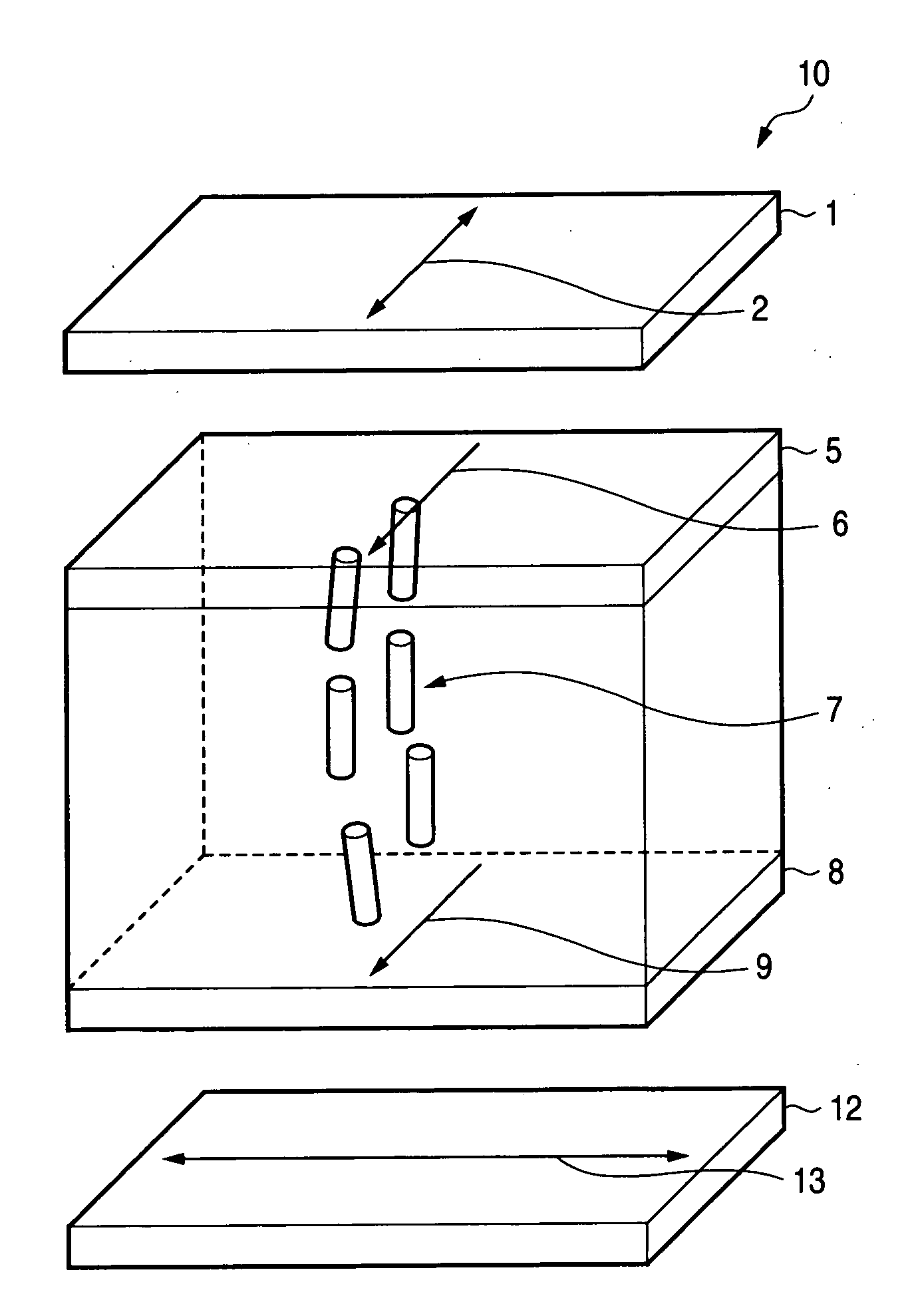
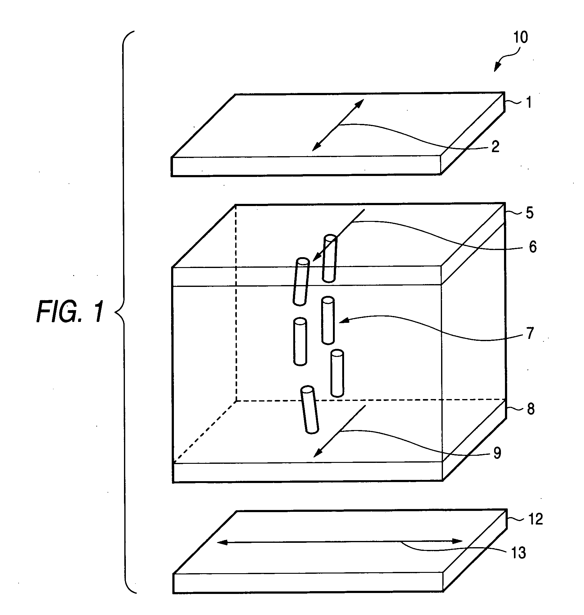
An optical compensation sheet is provided and includes: a cellulose acylate film having optical anisotropy and meeting all of requirements represented by the following expressions (1) to (3); and an optically anisotropic layer having a slow axis orthogonal to a slow axis of the cellulose acylate film. 2.6≦X+Y<3.0  Expression (1) 0≦X≦1.8  Expression (2) 1.0≦Y<3.0  Expression (3) X represents a substitution degree of acetyl group and Y represents a total sum of substitution degrees of propionyl, butanoyl, pentanoyl and hexanoyl groups.

Description

FIELD OF THE INVENTION [0001] The present invention relates to an optical compensation sheet, a polarizing plate and a liquid crystal display. BACKGROUND OF THE INVENTION [0002] Liquid crystal displays are expanding the range of their uses year after year because of their low power consumption and high space-saving rate as image display devices. Although great viewing-angle dependence of images and slow display response were major drawbacks to liquid crystal displays in the past, fast-response VA mode liquid crystal display models with wide viewing angles have recently been commercialized, and thereby the demand for liquid crystal displays is rapidly growing even in the market requiring high-quality images, such as the TV-set market. With this growing demand, further improvement in optical compensating power has been required for optical compensation members used in liquid crystal displays for the purpose of improving hue, contrast and viewing-angle dependences of these factors. [00...

Claims


Application Information

Patent Timeline
IPC IPC(8): G02F1/1335C09K19/00
CPCC08J5/18C08J2301/10G02B5/3083Y10T428/1041G02F1/1393Y10T428/1036G02F1/13363C09K2323/03C09K2323/031
Inventor MATSUFUJI, AKIHIRO
Owner FUJIFILM CORP
Learn More