Reflector device

Active Publication Date: 2006-10-05
MITSUBISHI ELECTRIC CORP
View PDF4 Cites 6 Cited by
  • Summary
  • Abstract
  • Description
  • Claims
  • Application Information

AI Technical Summary

Benefits of technology

[0008] The reflecting mirror apparatus in accordance with the present invention includes the reflecting mirror having the plurality of segmented mirrors arranged therein, the mirror cell for supporting this reflecting mirror, and the reference cell which is a rigid body disposed between the above-mentioned reflecting mirror and the above-mentioned mirror cell, and which serves as a reference surface used for control of the position of the above-mentioned reflecting mirror. Since the reflecting mirror apparatus controls the position of the reflecting mirror based on the reference cell according to this structure, it can perform positioning control on the reflecting mirror with high precision. The reflecting mirror apparatus in accordance with the present invention further includes the three reference cell support mechanisms disposed between the above-mentioned reference cell and the above-mentioned mirror cell, these reference cell support mechanisms restraining the above-mentioned reference cell both in the axial direction of the above-mentioned reflecting mirror and in the direction of the perimeter of the above-mentioned reflecting mirror. Since the reflecting mirror apparatus controls the position of the reflecting mirror based on the reference cell which is under little influence of the deformation of the mirror cell according to this structure, it can perform positioning control on the reflecting mirror with high precision. The reflecting mirror apparatus in accordance with the present invention further includes the force support mechanism disposed between the above-mentioned reference cell and the above-mentioned mirror cell, for canceling the self weight deformation of the above-mentioned reference cell. Furthermore, the above-mentioned force support mechanism has the axial lever which is disposed at the fulcrum on t

Problems solved by technology

However, when the reflecting mirror has an opening diameter of the order of several tens of meters or more, since there arises a manufacturing problem if the reflecting mirror consists of a single mirror, a technology for assembling one reflecting mirror by combining a plurality of mirrors (referred to segmented mirrors from here on) into which a single mirror is divided has been developed.
A problem with the reflecting mirror apparatus using such a related art supporting method is that since the direction of the optical axis is changed so as to fall within a driving range, a self weight deformation of the back structure resulting from a change in the attitude of the whole of the reflecting mirror apparatus, a deformation of the back structure due to the pressure of winds blowing against the reflecting mirror, and a deformation of the back structure which is caused by a temperature distribution which occurs therein degrades the mirror surface accuracy of the reflecting mirror consisting of the plurality of segmented mirrors.
A further problem is that since deformations which thus appear in the back structure may include not only a mode deformation which appears in the whole structure, but also a deformation which appears nonuniformly and locally in the back structure, the deformations are not canceled perfectly by using such a technique as shape maintenance control through estimation of the mode deformation, and therefore there cause displacements of the local positions of the plurality of segmented mirrors and the mirror surface accuracy of the reflecting mirror degrades.

Method used


Image

  • Reflector device
  • Reflector device
  • Reflector device

Examples


embodiment 1

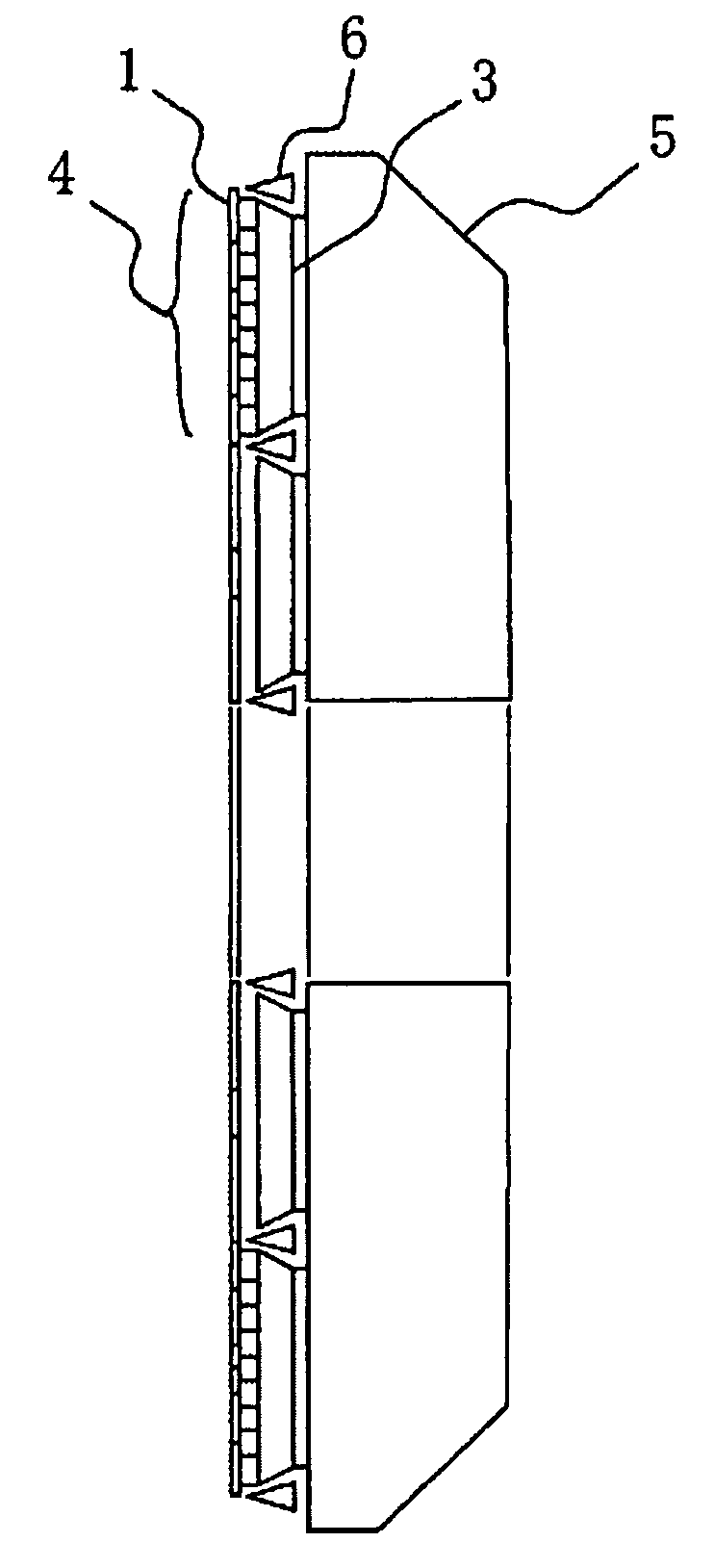
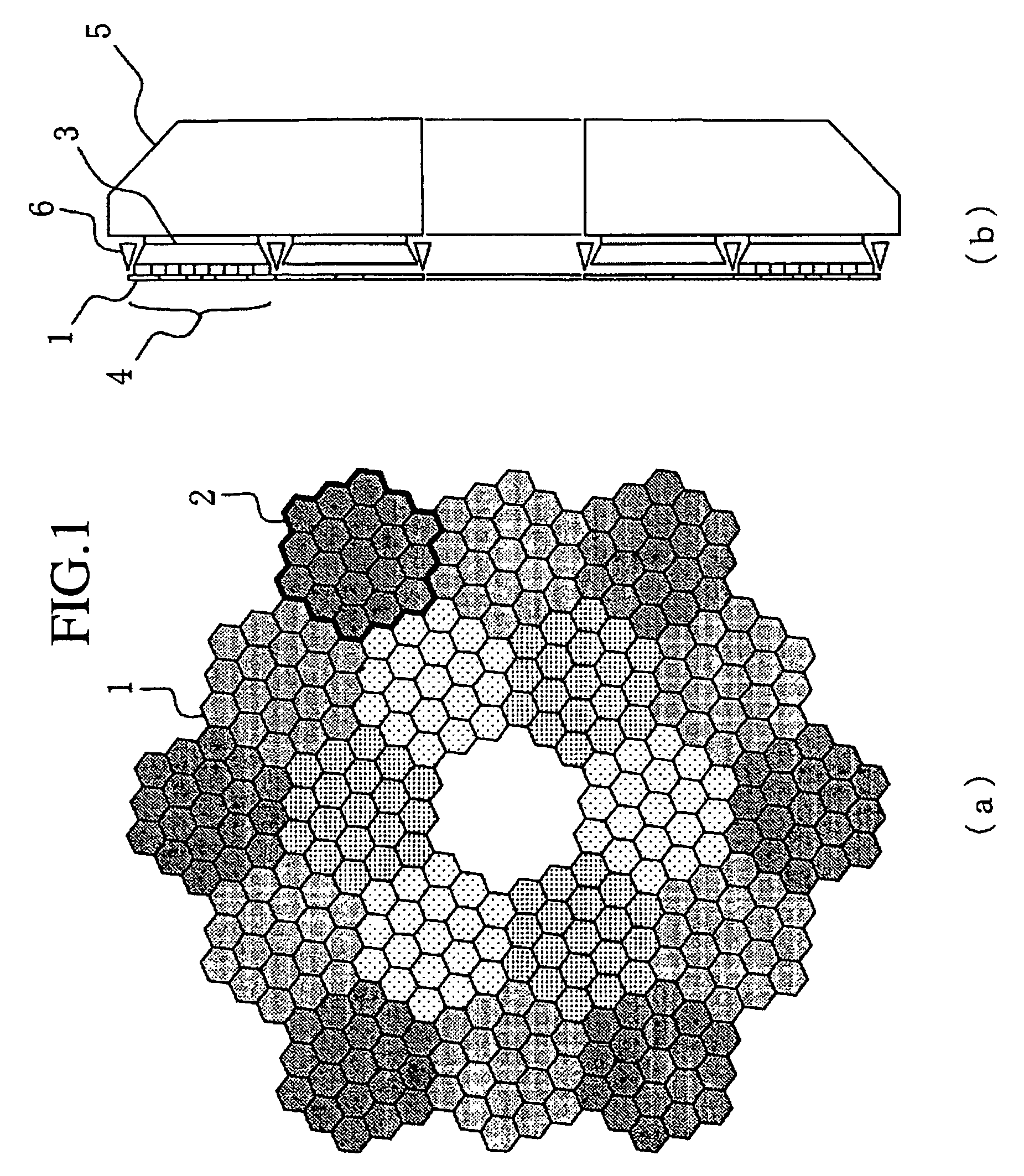
[0028] A reflecting mirror apparatus in accordance with embodiment 1 of the present invention will be explained with reference to FIGS. 1 to 5. FIG. 1 is a block diagram of the reflecting mirror apparatus in accordance with embodiment 1. FIG. 1(a) is a front view of the reflecting mirror apparatus, and FIG. 1(b) is a side view of the reflecting mirror apparatus. In FIG. 1, reference numeral 1 denotes a segmented mirror, and a plurality of segmented mirrors 1 are arranged on a reflecting mirror surface (for example, on a paraboloid-shaped surface or a paraboloid-shaped surface whose mirror surface is modified). Reference numeral 2 denotes a cluster mirror (i.e., an area surrounded by a thick line shown in FIG. 1) which consists of a plurality of segmented mirrors 1. In the example of FIG. 1, one cluster mirror 2 is formed of 19 segmented mirrors 1, and the reflecting mirror is formed of 18 cluster mirrors 2. Reference numeral 3 denotes a sub mirror cell for supporting a segmented mir...

embodiment 2

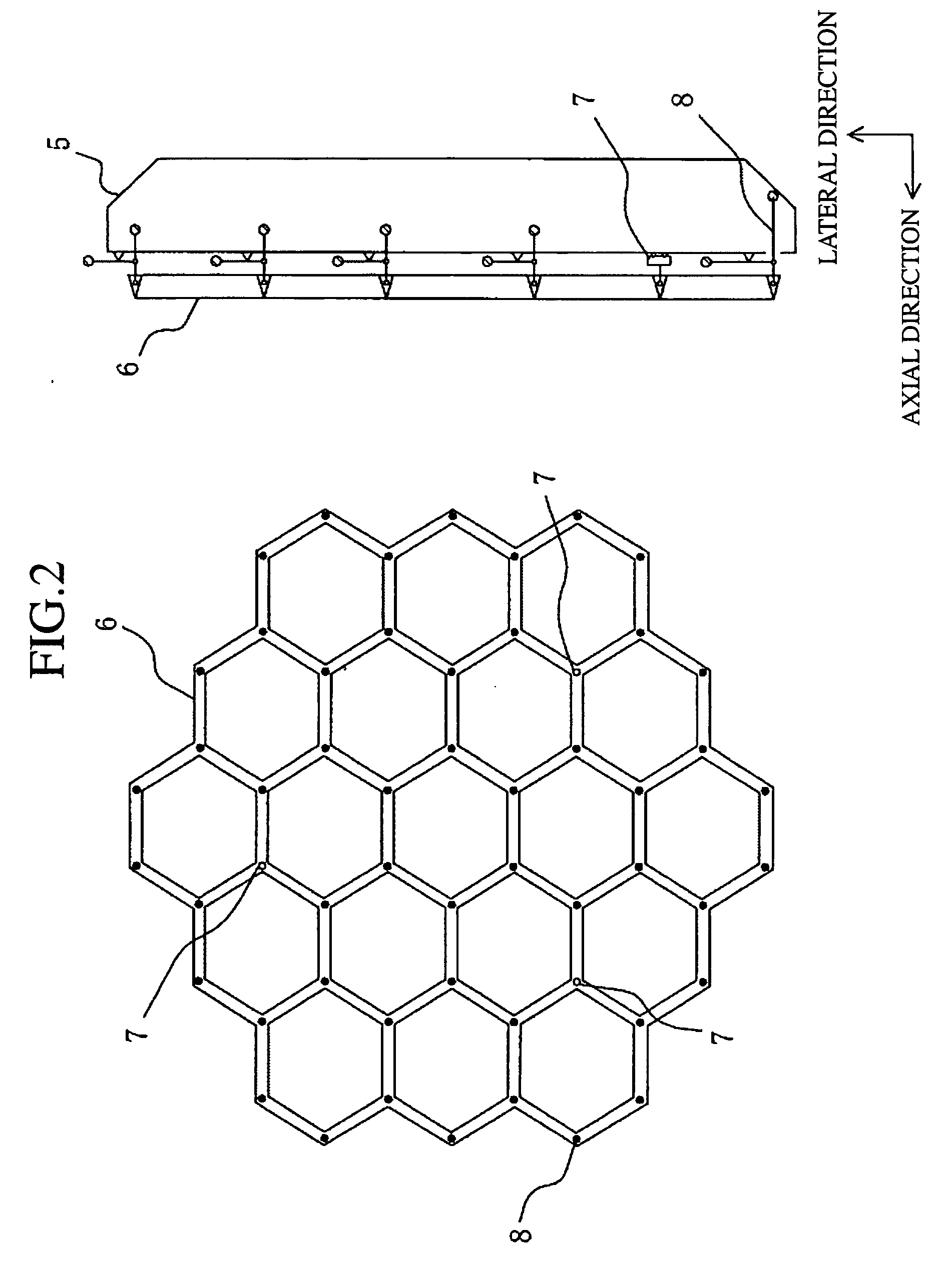
[0036] A reflecting mirror apparatus in accordance with embodiment 2 of the present invention will be explained with reference to FIGS. 6 and 7. FIG. 6 is a block diagram of the reflecting mirror apparatus in accordance with embodiment 2. In FIG. 6, reference numeral 23 denotes a fluid pressure support mechanism, and this fluid pressure support mechanism 23 is disposed in a mirror cell 5 for supporting a reference cell 6 using a fluid pressure. A plurality of fluid pressure support mechanisms 23 are arranged in the mirror cell 5 so as to support a plurality of joints of the reference cell 6, respectively. In the reflecting mirror apparatus, the mirror cell 5, reference cell 6, and force support mechanisms 8 shown in FIG. 5, and the fixing support mechanisms 7 which are not shown in FIG. 6 are replaced by the mirror cell 5, reference cell 6, and fluid pressure support mechanisms 23 shown in FIG. 6. Even the reflecting mirror apparatus having this structure can carry out control of th...


PUM


Abstract

In a reflecting mirror, a plurality of segmented mirrors are grouped into a plurality of groups of a cluster, and are supported by a plurality of sub mirror cells. The plurality of sub mirror cells are supported by a mirror cell, and all the segmented mirrors are supported by the mirror cell. A reference cell is supported by a plurality of force support mechanisms disposed in the mirror cell with the reference cell being nearly in a weightlessness state. Projections and depressions are prevented from occurring in an axial direction of the reflecting mirror due to a self weight deformation, and the reference cell can be used as a reference surface for control of the positions of the plurality of segmented mirrors and those of the plurality of cluster mirrors in the axial direction of the reflecting mirror.

Description

FIELD OF THE INVENTION [0001] The present invention relates to a reflecting mirror apparatus which is used for a large-sized telescope which receives observation light, millimeter waves, and submillimeter waves from celestial bodies so as to make celestial observations, and which supports the mirror surface of a reflecting mirror consisting of a plurality of segmented mirrors with high precision. BACKGROUND OF THE INVENTION [0002] Recent years have seen increasingly advances in upsizing of a telescope system which receives observation light and electric waves from space so as to make celestial observations, in order to carry out highly precise observation with a higher resolution. Especially, the dominating telescope system has a reflecting mirror which consists of a single mirror when its opening diameter is of the order of several meters. However, when the reflecting mirror has an opening diameter of the order of several tens of meters or more, since there arises a manufacturing p...

Claims


Application Information

Patent Timeline
IPC IPC(8): G02B7/182
CPCG02B23/06G02B7/183
Inventor OSHIMA, TAKEHARUITO, NOBORU
Owner MITSUBISHI ELECTRIC CORP
Why Eureka
Try Eureka