Air intake device for watercraft

a technology for air intake devices and watercraft, which is applied in the direction of air cleaners and silencer combinations, special purpose vessels, combustion air/fuel air treatment, etc. it can solve the problems of easy leakage of engine noise through the insufficient straightening of the air flow in and the inability to control the length of the air intake duct. to achieve the effect of suppressing noise generation and good intake efficiency

Inactive Publication Date: 2006-10-05
HONDA MOTOR CO LTD
View PDF2 Cites 7 Cited by
  • Summary
  • Abstract
  • Description
  • Claims
  • Application Information

AI Technical Summary

Benefits of technology

[0011] It is accordingly an object of the present invention to provide an air intake device for a watercraft which can suppress noise generating from an intake system of an engine and can obtain good intake efficiency.

Problems solved by technology

Accordingly, there is little room of controlling the length of the air intake duct, and the flow of air in the air intake duct cannot be sufficiently straightened.
Further, since the length of the air intake duct is short, noise from the engine easily leaks through the air intake duct.
The higher the temperature of an intake air, the lower the intake efficiency of the engine, causing an adverse effect on the output from the engine.

Method used


Image

  • Air intake device for watercraft
  • Air intake device for watercraft
  • Air intake device for watercraft

Examples


Embodiment Construction

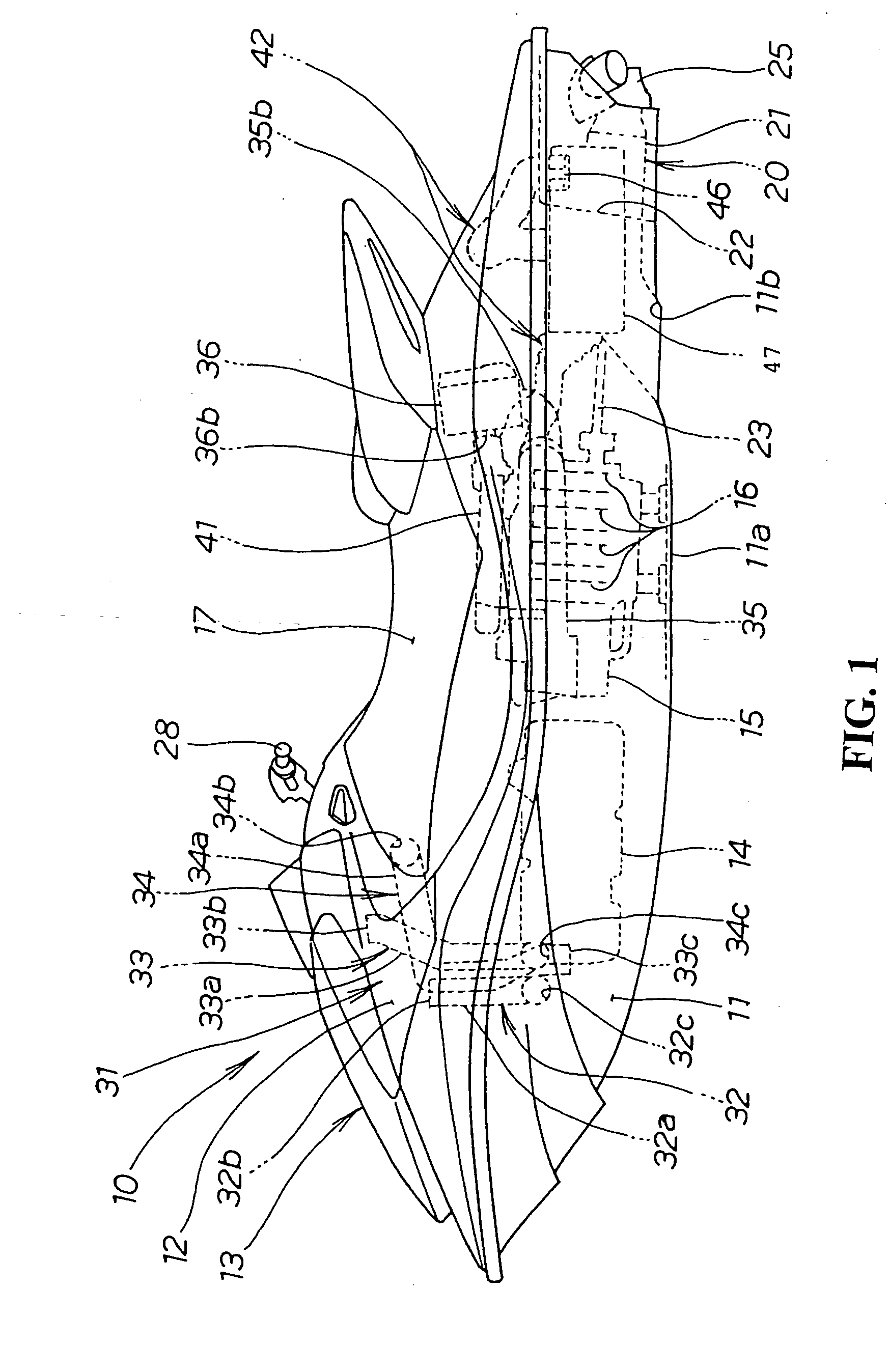
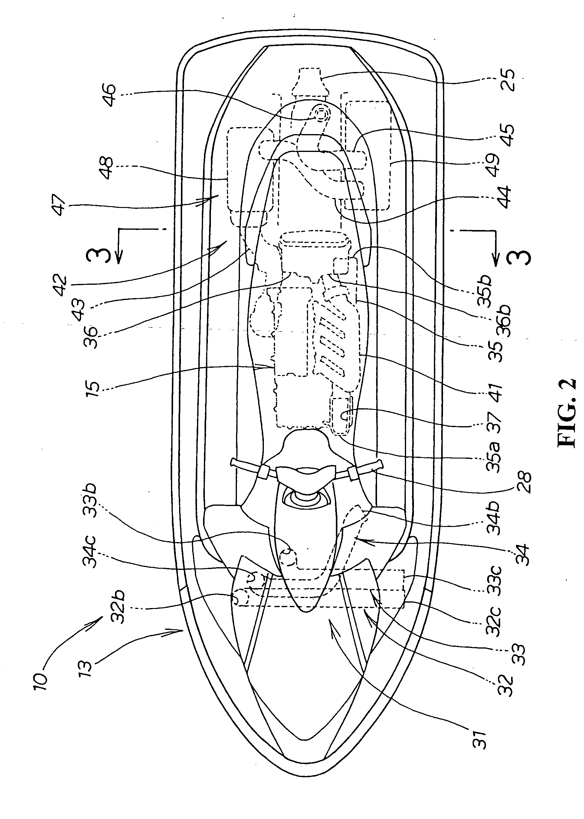
[0031]FIG. 1 is a side view of a watercraft according to the present invention.

[0032] The watercraft 10 (which will be hereinafter referred to also as jet propulsion boat 10) has a watercraft body 13 composed of a hull 11 forming a watercraft bottom 11a (which will be hereinafter referred to also as boat bottom 11a) and a deck 12 covering the upper side of the hull 11. A fuel tank 14 is provided in the watercraft body 13, and an engine 15 is located on the rear side of the fuel tank 14. A saddle seat 17 is located on the upper side of the engine 15, and a jet pump 20 is located on the rear side of the engine 15. A steering handle 28 is located on the upper side of the fuel tank 14.

[0033] The engine 15 has four cylinders 16 formed substantially upright and arranged in a straight line extending in the longitudinal direction of the watercraft body 13.

[0034] The jet pump 20 has a pump housing 21 extending rearward from an opening 11b of the boat bottom 11a constituting the hull 11. A...


PUM


Abstract

An air intake device for a watercraft adapted to suppress noise generating from an intake system of an engine and can obtain good intake efficiency. The air intake device includes intake ports opening to a side surface of the engine, and an air cleaner located on the rear side of the engine. An outlet of the air cleaner is connected through an intake passage to the intake ports of the engine. An air duct extends from an inlet of the air cleaner along the side surface of the engine to the position corresponding to the front end of the engine. The air duct has a front opening that faces downward.

Description

CROSS-REFERENCE TO RELATED APPLICATION [0001] The present application claims priority under 35 U.S.C. §119 to Japanese Patent Application No. 2005-095171, filed Mar. 29, 2005, the entire contents of which are hereby incorporated by reference. BACKGROUND OF THE INVENTION [0002] 1. Field of the Invention [0003] The present invention relates to an improvement in an air intake device for an engine in a watercraft. [0004] 2. Description of Background Art [0005] Conventionally known is an air intake structure for an engine in a compact water gliding boat having a boat body in which the engine is provided and an air cleaner located on the rear side of the engine (see for example Japanese Patent Laid-Open No. 2004-52681 (FIGS. 3 and 4)). [0006] FIG. 3 in Japanese Patent Laid-Open No. 2004-52681 is a schematic view of an engine E as viewed from the right side of a compact water gliding boat (reference characters or numerals cited herein are those shown in this publication). The engine E has ...

Claims


Application Information

Patent Timeline
Patent Type & Authority Applications(United States)
IPC IPC(8): F02B61/04
CPCF02M35/02F02M35/168F02M35/14F02M35/10275
Inventor NODA, YOSHIAKIMATSUMOTO, MASATSUGU
Owner HONDA MOTOR CO LTD
Why Eureka
Try Eureka