
Layout verification method and layout design unit

Inactive Publication Date: 2006-10-05
FUJITSU MICROELECTRONICS LTD
View PDF12 Cites 10 Cited by
  • Summary
  • Abstract
  • Description
  • Claims
  • Application Information

AI Technical Summary

Benefits of technology

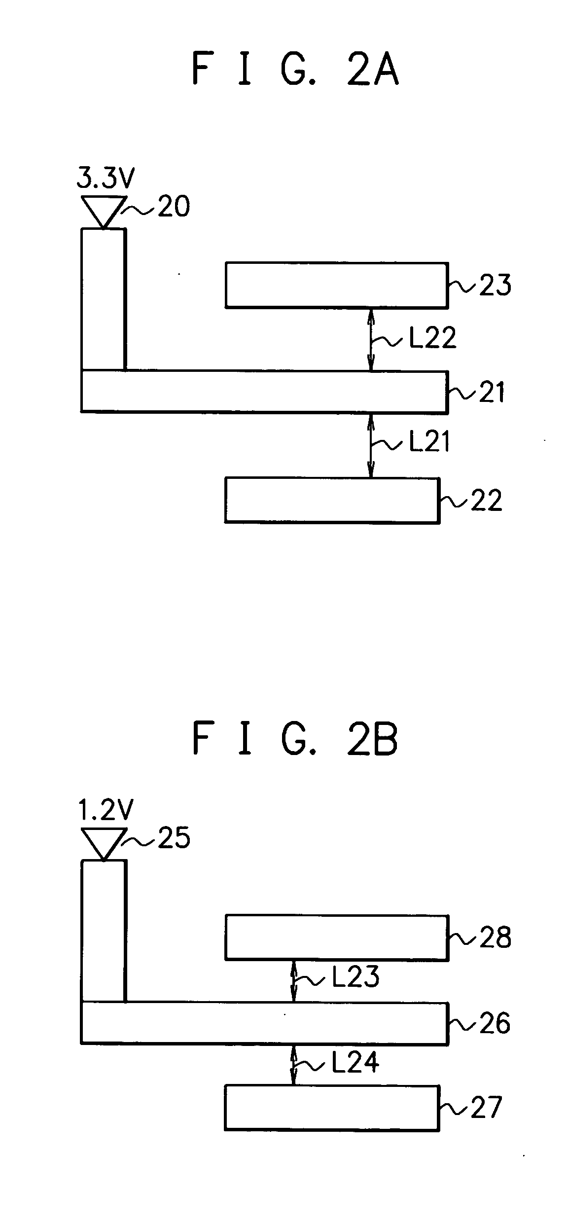
[0013] An object of the present invention is to make it possible to perform a layout rule verification of the clearance between wires, the clearance between a wire and an element, etc. in accordance with the used voltage using only layers used in an actual process.
[0015] According to the present invention, the circuit component to which a high voltage is applied is separately arranged in a specific layer, thereby making it possible to recognize the circuit component, to which a high voltage is applied, on the layout, and to perform the layout verification.
[0017] According to the present invention, the circuit element to which a high voltage may be applied is recognized from the layer or a combination of the layers, and the circuit component connected hereto is recognized as a circuit component to which a high voltage is applied, thereby making it possible to recognize the circuit component, to which a high voltage is applied, on the layout, and to perform the layout verification.

Problems solved by technology

Conventionally, however, even though some voltages, more or less, were applied to a wire etc. on the layout, it was impossible to perform a layout rule verification in accordance with the used voltage, that is, a so-called design rule check (DRC) because there was no method for recognizing the voltage, which is applied, from the layout.

Method used


Image

  • Layout verification method and layout design unit
  • Layout verification method and layout design unit
  • Layout verification method and layout design unit

Examples


first embodiment

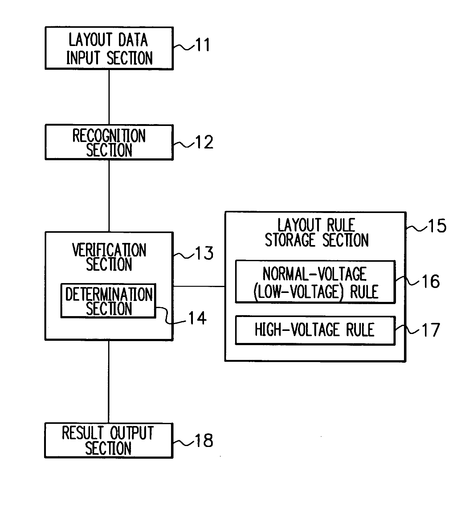
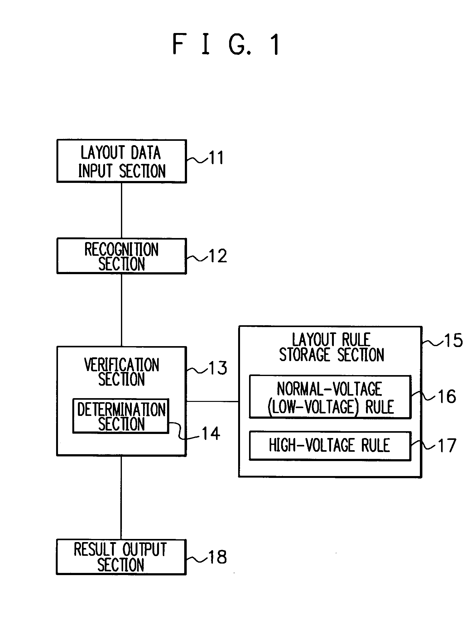
[0027]FIG. 1 is a block diagram showing a configuration example of a layout verifier according to a first embodiment of the present invention. As shown in FIG. 1, the layout verifier in the first embodiment has a layout data input section 11, a recognition section 12, a verification section 13, a layout rule storage section 15, and a result output section 18.

[0028] The layout data input section 11 inputs layout data of an integrated circuit.

[0029] In the integrated circuit of this embodiment, plural voltages having different voltage values are used in its interior, and as shown in FIG. 2, which will be described later, plural layers in which circuit components of the integrated circuit are laid out for arrangement are provided. In this embodiment, the plural layers are provided in accordance with the used voltages, and components such as a metal wire, polysilicon used as a wire and a via to which a high voltage is applied are arranged in a specific layer. Hereinafter, for simplici...

second embodiment

[0046] Next, a second embodiment of the present invention is explained.

[0047] In the second embodiment to be explained below, the circuit elements such as, for example, a specific element, a well having a high voltage applied, and a power supply, which have the possibility of being used at a high voltage, i.e. to which a high voltage may be applied, are recognized from the layer or the combination of layers. Then, the wire including polysilicon which is an equivalent node hereto and a resistive element is recognized as one to which a high voltage is applied, that is, the circuit component electrically connected to the circuit element to which a high voltage may be applied is recognized as one to which a high voltage is applied.

[0048] The integrated circuit in this embodiment is also an integrated circuit in which plural voltages of which the value is different in its interior are used, and plural layers are provided, in which the circuit components of the integrated circuit are la...


PUM


Abstract

By providing plural layers in which circuit components of an integrated circuit using plural voltages are arranged in accordance with used voltages, separately arranging the circuit component to which a high voltage is applied in a specific layer among the plural layers, recognizing the used voltage for each layer, and performing a layout verification by applying a condition in accordance with the used voltage, it is possible to recognize the circuit component, to which a high voltage is applied, on the layout, and to perform the layout verification using a layout rule in accordance with the used voltage using only the layers used in an actual process without newly generating a dummy layer etc.

Description

CROSS-REFERENCE TO RELATED APPLICATIONS [0001] This application is based upon and claims the benefit of priority from the prior Japanese Patent Application No. 2005-102718, filed on Mar. 31, 2005, the entire contents of which are incorporated herein by reference. BACKGROUND OF THE INVENTION [0002] 1. Field of the Invention [0003] The present invention relates to a layout verification method and a layout design unit for an integrated circuit in which elements and wires using different voltages exist concurrently. [0004] 2. Description of the Related Art [0005] In designing a large-scale integrated (LSI) circuit etc., it is necessary to change a layout rule on an LSI design in accordance with a voltage to be applied (used voltage). For example, the layout rule specifies a clearance between metal wires, a clearance between a wire including polysilicon used as a wire and an element region as shown in FIG. 8, etc., which are provided in order to prevent the dielectric breakdown of an int...

Claims


Application Information

Patent Timeline
IPC IPC(8): G06F17/50
CPCG06F17/5081G06F30/398
Inventor DEURA, MANABU
Owner FUJITSU MICROELECTRONICS LTD
Learn More