Disk cutter having tip inserts coated with a hard material

a technology of hard material and disk cutter, which is applied in the direction of band saws, manufacturing tools, saw chains, etc., can solve the problems of insufficient adhesion of hard material to the surface of each tip insert, and the durability of the disk cutter, so as to prolong the life and improve the adhesion of hard material

Inactive Publication Date: 2006-10-12
TENRYU SAW MFG
View PDF4 Cites 21 Cited by
  • Summary
  • Abstract
  • Description
  • Claims
  • Application Information

AI Technical Summary

Benefits of technology

[0007] It is therefore an object of the present invention to provide a disk cutter which can improve the adhesion of a hard material to the surface of each tip insert, thereby extending the life.

Problems solved by technology

However, in such a disk cutter that the surface of each tip insert is simply coated with a hard material, the adhesion of the hard material to the surface of each tip insert is insufficient.
Accordingly, when steel such as stainless steel is cut for a long time by using this disk cutter, there is a case that the hard material may separate from the surface of each tip insert, thus causing a problem in durability of the disk cutter.

Method used


Image

  • Disk cutter having tip inserts coated with a hard material
  • Disk cutter having tip inserts coated with a hard material
  • Disk cutter having tip inserts coated with a hard material

Examples


Embodiment Construction

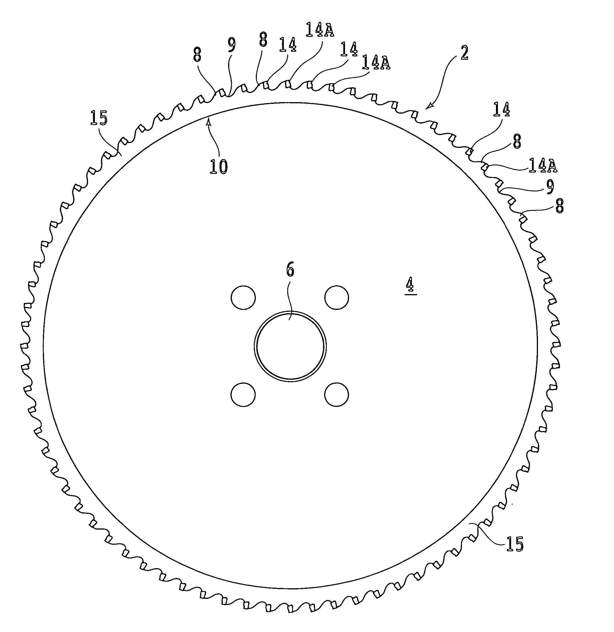
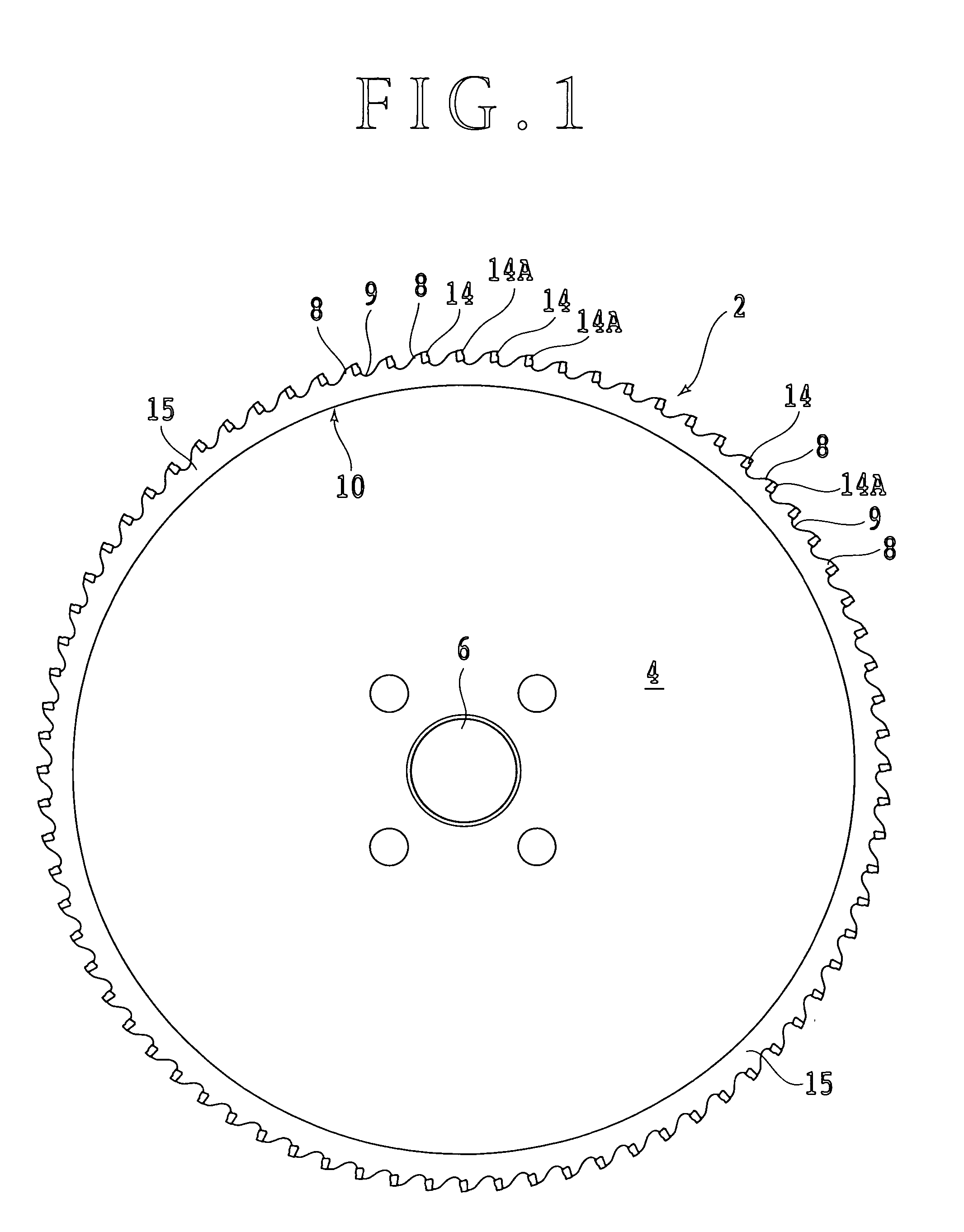
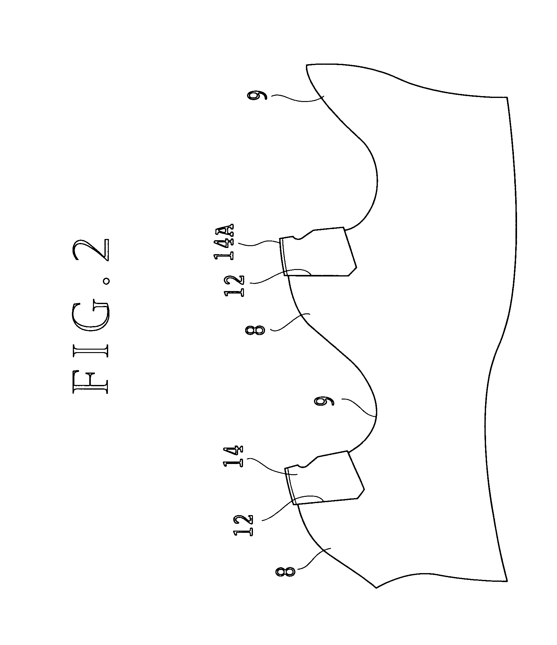
[0021] Referring to FIG. 1, there is shown a side view of a disk cutter 2 according to a preferred embodiment of the present invention. The disk cutter 2 is suitable for cutting of steel such as austenitic stainless steel, ferritic stainless steel, and martensitic stainless steel. The disk cutter 2 includes an annular disk-shaped base (base disk) 4 having a thickness of about 1.7 mm and a plurality of (e.g., 72) saw-toothed tip supports 8 formed along the outer circumference of the base disk 4 at equal intervals. A gullet 9 is defined between adjacent ones of the tip supports 8. The base disk 4 is formed of steel such as JIS SKS5 (alloy tool steel), JIS SK5 (carbon tool steel), or JIS SK6 (carbon tool steel). The diameter of the base disk 4 is about 250 mm, for example, and the base disk 4 has a central hole 6 having a diameter of about 32 mm, for example. However, these values are merely illustrative, and the disk cutter of the present invention is not limited to this preferred emb...


PUM

PropertyMeasurementUnit
particle sizeaaaaaaaaaa
thicknessaaaaaaaaaa
thicknessaaaaaaaaaa

Abstract

A disk cutter including an annular disk-shaped base adapted to be driven about an axis of rotation, a plurality of tip supports formed along the outer circumference of the base integrally therewith so that a gullet is defined between adjacent ones of the tip supports, a plurality of tip inserts respectively fixed to the tip supports, and a TiAlN coating formed on the surface of each tip insert. Each tip insert is formed of a sintered alloy composed of 98 to 90 w % of WC powder having a particle size of 0.1 to 0.8 μm and 2 to 10 w % of Co powder. The TiAlN coating has a thickness of 1 to 5 μm.

Description

BACKGROUND OF THE INVENTION [0001] 1. Field of the Invention [0002] The present invention relates generally to a disk cutter, and more particularly to a disk cutter or circular saw suitable for cutting of steel such as stainless steel. [0003] 2. Description of the Related Art [0004] A disk cutter or circular saw including a base disk having a plurality of tip supports arranged along the outer circumference and a plurality of hardened cutting tip inserts (cutter inserts) respectively fixed to the tip supports by brazing or the like is frequently used for cutting of steel or the like. The tip supports are spaced at given intervals in the circumferential direction of the base disk or annular disk-shaped base, and a gullet is defined between adjacent ones of the tip supports. [0005] Each tip support has a recess, and each cutting tip insert is fixed in the recess of the corresponding tip support by brazing or the like. The base disk has a mounting hole at its central portion, and a rota...

Claims


Application Information

Patent Timeline
Patent Type & Authority Applications(United States)
IPC IPC(8): B23D57/00
CPCB22F2005/001C23C30/005C22C29/08B23D61/04Y10T83/9319
Inventor HASEGAWA, SEIICHITANIFUJI, JUNICHI
Owner TENRYU SAW MFG
Why Eureka
Try Eureka