Hybrid transonic-subsonic aerofoils

a technology of aerofoils and transonics, applied in the field of hybrid transonic subsonic aerofoils, can solve the problems of premature formation of shock waves on the upper surface of airfoils, induced boundary layer separation, transonic flight of high-speed air vehicles, etc., to improve the subsonic performance, improve the transonic performance, and suffer a small loss of subsonic performance.

Active Publication Date: 2006-10-12
ISRAEL AEROSPACE IND
View PDF13 Cites 20 Cited by
  • Summary
  • Abstract
  • Description
  • Claims
  • Application Information

AI Technical Summary

Benefits of technology

[0047] Thus, according to the invention, a method is provided for designing a hybrid subsonic-transonic aerofoil section, in which a basic subsonically-designed aerofoil may be modified, in particular the mid-portion thereof according to transonic design rules or procedures, such that the resulting aerofoil has improved transonic performance over the original subsonic aerofoil, while maintaining, improving, or in some cases suffering a small loss in subsonic performance.
[0048] Also, according to the invention, a method is provided for designing a hybrid subsonic-transonic aerofoil section, in which a basic transonically-designed aerofoil is modified, in particular the upstream portion thereof according to subsonic design rules or procedures, such that the resulting aerofoil has improved subsonic performance over the original transonic aerofoil, while maintaining, improving, or in some cases suffering a small loss in transonic performance.

Problems solved by technology

There is a well known basic conflict between efficient transonic flight of high-speed air vehicles and requirement for high-lift performance at subsonic speeds.
At transonic speeds, there is a general tendency for premature formation of shock waves on the upper surface of airfoils and for the development of shock-induced boundary layer separation.
The resulting drag penalties and limitations on available lift (buffet and maximum lift limits) adversely affect the performance of the aircraft and constrain the allowable lift envelope.
However, as is well known, this type of camber distribution, while being beneficial at transonic Mach numbers nevertheless generates a sharp suction peak at subsonic Mach numbers, which in turn triggers premature flow separation, particularly with increases in angle of attack, and limits the lift-carrying capabilities of supercritical airfoils at subsonic Mach numbers.
Nevertheless, this solution is not always desirable, being mechanically complex, and carrying associated cost and maintenance elements, rendering it unsuitable for many applications, including, for example, UAV applications.
However, high-lift subsonic airfoils are unsuitable and cannot operate at medium and high transonic Mach numbers because of premature formation of shock waves on their upper and lower surfaces, and the resulting fast deterioration of their lift-carrying capabilities with increasing Mach numbers.
Thus, the known groups of single-element, high-lift airfoils target a specific range of Mach numbers for their best lift performance, compromising on characteristics at off-design flight conditions.

Method used


Image

  • Hybrid transonic-subsonic aerofoils
  • Hybrid transonic-subsonic aerofoils
  • Hybrid transonic-subsonic aerofoils

Examples


example 1

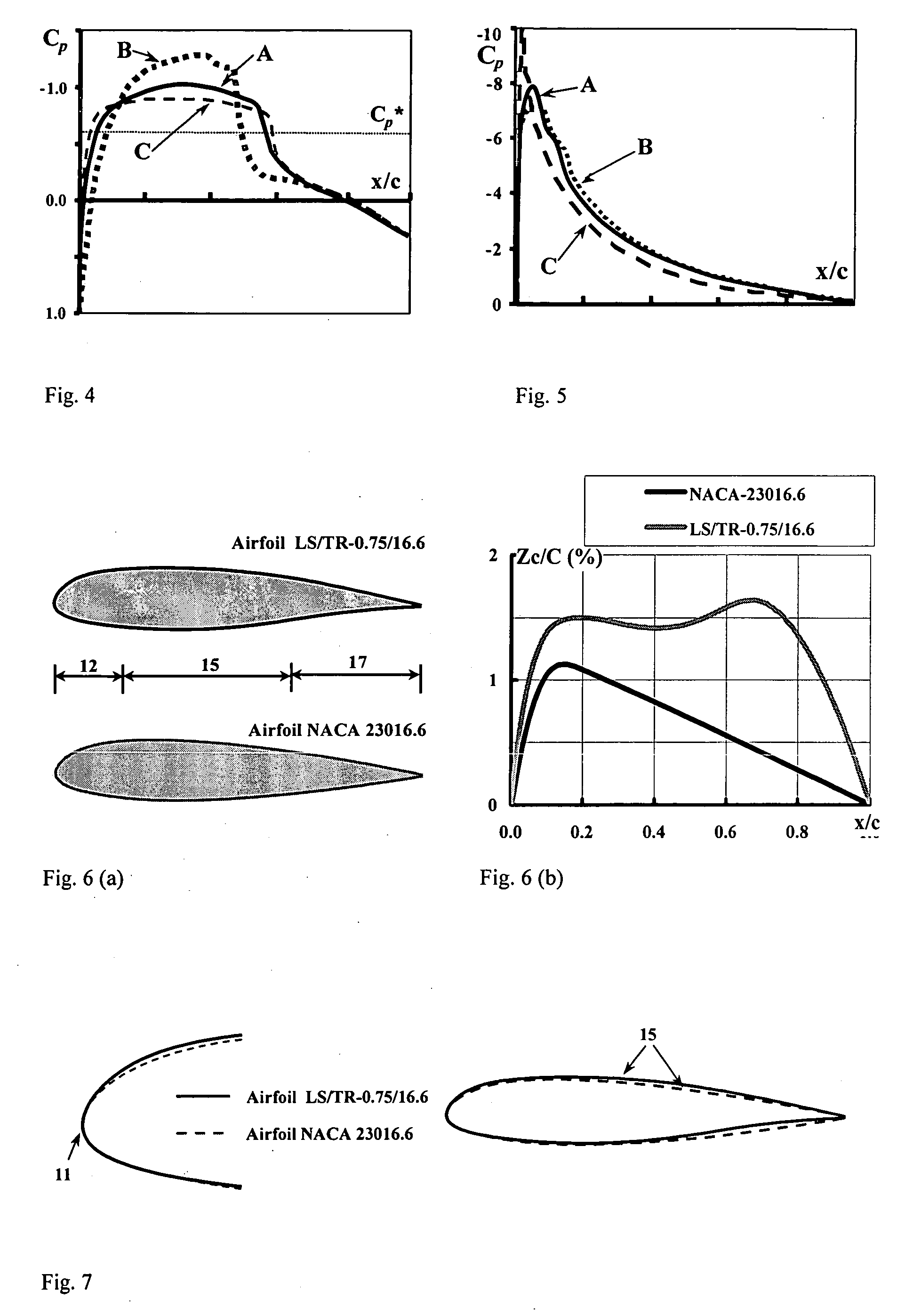
[0100] A low lift hybrid airfoil according to the invention is illustrated in FIG. 6(a), designated herein as LS / TR-0.75 / 16.6, and is geometrically compared with a subsonic airfoil NACA-23016.6 that was chosen as reference case for illustrating some aerodynamic features of the invention. FIG. 6(b) compares the camber distributions of the two aerofoils. The airfoil LS / TR-0.75 / 16.6 was designed for high transonic cruise Mach number of M=0.75, relatively small design lift coefficient of Cl=0.1, Reynolds Number Re=3.0*106, constrained pitching moment and maximum thickness of t / cmax=16.6%. The subsonic design point was not fully fixed, but rather allowed to float, such as to provide the best possible design lift coefficient (if possible, better than that of the NACA reference aerofoil) at a Mach number of about 0.1. The hybrid aerofoil LS / TR-0.75 / 16.6 was designed using NACA-23016.6 as a starting point, and using trial and error techniques for providing the requires aerodynamic performan...

example 2

[0103] In this example, two high-lift, hybrid airfoils, designated as HC-0.7 / 13.8A and HC-0.7 / 13.9B, which differ one from the other in the relative bluntness of their leading edges, though more in their camber distributions, are illustrated in FIG. 10, compared with a datum or reference transonic aerofoil TC-07 / 13.8 that was specially designed for the same flight conditions. The transonic design point was set at M=0.7, design lift coefficient of 0.7, (Re=1.5*106), t / c=13.8%; the subsonic design point was set at Mach number of between about 0.1 and about 0.2, t / c=13.9%, with design lift coefficient left undefined, the design of the aerofoils being such as to maximize this parameter.

[0104] The reference transonic aerofoil TC-07 / 13.8 was designed using standard design methodology of transonic airfoils, in particular supercritical technology adjusted to incorporate the design principles of NLF (natural laminar flow airfoils) airfoils, for the design point M=0.7, design lift coefficien...


PUM


Abstract

A hybrid transonic-subsonic airfoil is provided that combines subsonic and transonic features for achieving simultaneously acceptable aerodynamic characteristics at low subsonic and high transonic Mach numbers.

Description

[0001] This application claims the benefit of prior U.S. provisional patent application No. 60 / 637,464 filed Dec. 21, 2004, the contents of which are hereby incorporated by reference in their entirety.FIELD OF THE INVENTION [0002] This invention relates to aerofoils, to wings based on such aerofoils, and to air vehicles comprising such wings or aerofoils. BACKGROUND OF THE INVENTION [0003] There is a well known basic conflict between efficient transonic flight of high-speed air vehicles and requirement for high-lift performance at subsonic speeds. Essentially there exist some basic differences in the aerodynamics associated with transonic and subsonic Mach numbers, and in the resulting pressure distributions on wing sections at the different flight regimes. [0004] At transonic speeds, there is a general tendency for premature formation of shock waves on the upper surface of airfoils and for the development of shock-induced boundary layer separation. The resulting drag penalties and ...

Claims


Application Information

Patent Timeline
Patent Type & Authority Applications(United States)
IPC IPC(8): B64C3/14
CPCY02T50/12B64C3/14Y02T50/10
Inventor SHEPSHELOVICH, MICHAELSTEINBUCH, MOSHE
Owner ISRAEL AEROSPACE IND
Why Eureka
Try Eureka